NE592 has typ. 12uV RMS input noise from 1kHz to 10MHz. How many uV/sqrt(Hz) is it? The sqrt(10MHz)=3162 sqrt(Hz). That's 3.8nV/sqrt(Hz). Since the input impedance is 560 || 680, which is 307, that corresponds to current noise i=12.3pA/sqrt(Hz).
How much DC current generates shot noise like this? i=sqrt(2qI). i^2=2qI. I=i^2/2q=473uA.
|
SFH203 capacity at 12VDatasheet says 11pF @0V. Since diode capacity is proportional to square root of applied voltage+0.7 V. Therefore at 12V, it is 11pF/sqrt((12+0.7)/0.7)=2.6pF. | |||||||||||||||||||||||||||||||||||
Warning: include(../sim/fe.data): failed to open stream: No such file or directory in /home/clock/www/twibright.com/ronja/technotes/mundaka_frontend.php on line 22

Warning: include(): Failed opening '../sim/fe.data' for inclusion (include_path='.:/usr/share/php:/usr/share/pear') in /home/clock/www/twibright.com/ronja/technotes/mundaka_frontend.php on line 22
| Noise Source | If the unit current signal were injected into the input instead the noise source, how many times would the output amplitude be bigger @10MHz? | Equivalent shot noise DC current produced by the noise source | Equivalent shot noise DC current as if produced by the input @10MHz | Noise spectral character as if produced by the input | Total inband contribution (blue sources have weight 1/3, white ones 1/1) |
| Photodiode dark current | 1 | 5nA | 5nA | white | 5nA |
| 100k | 1 | 520nA | 520nA | white | 520nA |
| 2.2M | im(G1)/im(G2)=0.95 | 23.6nA | 26nA | white | 26nA |
| 25 Ohm | im(G1)/im(G3)=245 | 2.08mA | 35nA | blue | 12nA |
| MOSFET | im(G1)=79.3 | 840uA | 134nA | blue | 45nA |
| 211 Ohm | im(G1)=79.3 | 246uA | 39nA | blue | 13nA |
| 680 Ohm | im(G1)=79.3 | 76uA | 12nA | blue | 4nA |
| NE592 | im(G1)=79.3 | 473uA | 75nA | blue | 25nA |
| Total | 650nA | ||||
|
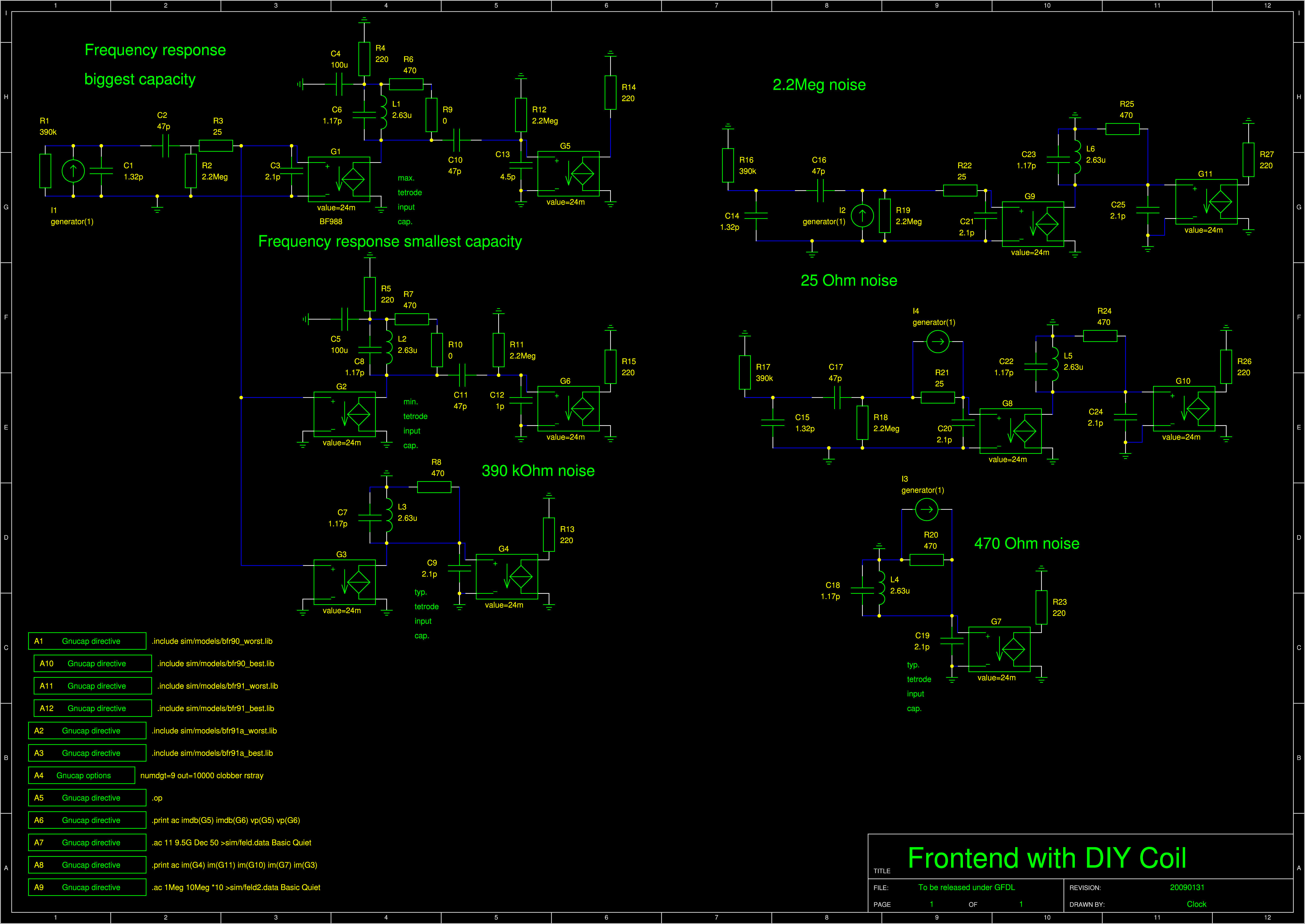
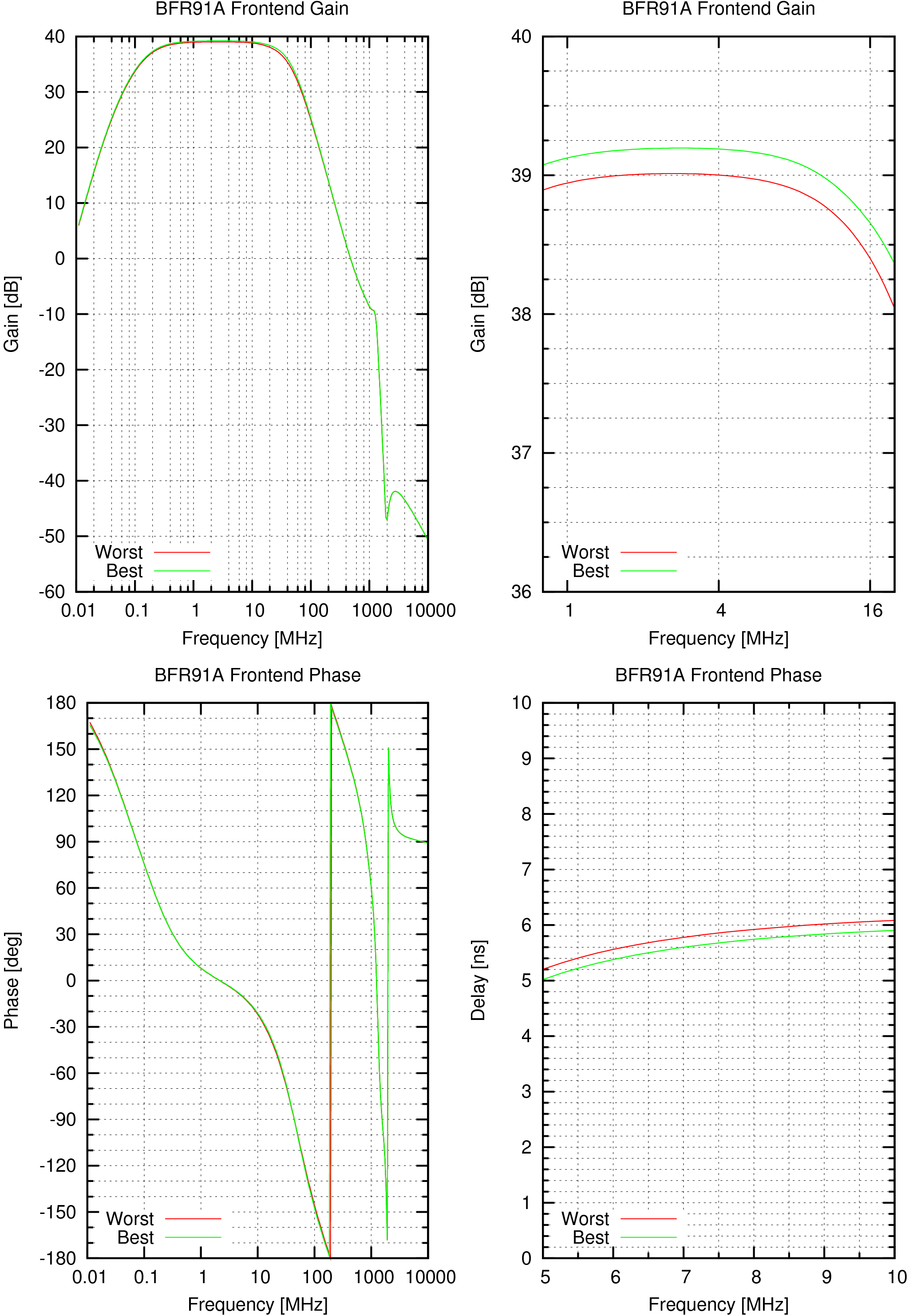
The frontend has two stages. The first one integrates the signal, the second one derivates. The derivator actually needs only a capacitor in the emitter but the transistor makes a hump on the characteristic probably because impedance gyration. To fix this the gain is reduced by a series resistor and the R and C are optimized to get the desired spectral curve. The highpass produces a serious delay between 5 and 10 MHz so I have extended the frequency downwards which makes it better. During that the 100k resistor for the photodiode was not enough. So I put a 390k there and the photodiode will be fed from 48V, decreasing the capacitance, noise and improving the range by 30%. | |||||||||||||||||||||||||||||||||||
|
|
I don't use the usual noise density, but equivalent DC current generating shot noise instead. These currents can be ordinarily added without a square root. However if the signal goes through and amplifier with gain A, the number doesn't increase with A but with A^2.
The noise current for shot noise is sqrt(2*q*I*BW). For thermal noise it's qrt(4*k*T*BW/R). q is the electron charge, BW bandwidth, T temperature, k Boltzmann constant. We get the equivalent DC current is 2*Ut/R, where Ut is the thermal voltage kT/q=26mV (room temp.) We get Iesn=52mV/R.
For MOSFET the inverse of transconductance 1/gm is taken istead of R and the noise has to be multiplied by 2/3 see Noise Sources in a MOSFET. We get Iesn=35mV/R.
Noise contribution of a resistor MOSFET or semiconductor junction is calculated using the next following interstage connection (capacitor, wire etc.). We know how many times the PD current is magnified there and we also insert a generator side by side to the examined noisy element and calculate how many times this injected current will be magnified there. Then we divide to get equivalent contribution to the input. We also have to square if we are calculating with equivalent DC shot noise currents.
#Freq           im(C3)         im(G1)         im(C7)         im(L15)        im(G2)         im(L53)
 10.E+6         0.603567587    109.78308      6.74372652     87.1679398     112.86639      1.26042028
When calculating the noise in the differential amplifiers, we are drawing the circuit for only one half. We are concerned how the signal on one capacitor is amplified and appears again on one capacitor. But each capacitor gets contribution from two noisy transistor. Therefore in this model, we have to calculate with double the current, or the total current source current (instead of 2.5mA 5mA etc.).
But - here we see the 3mA current of the derivator contributes 137nA noise to the input and becomes the major noise source! We have to diminish the current as much as possible! Unfortunately even decreasing it to 361uA produces 147nA noise with a small drop for collector currents somewhere in between. This doesn't seem to be a good way!
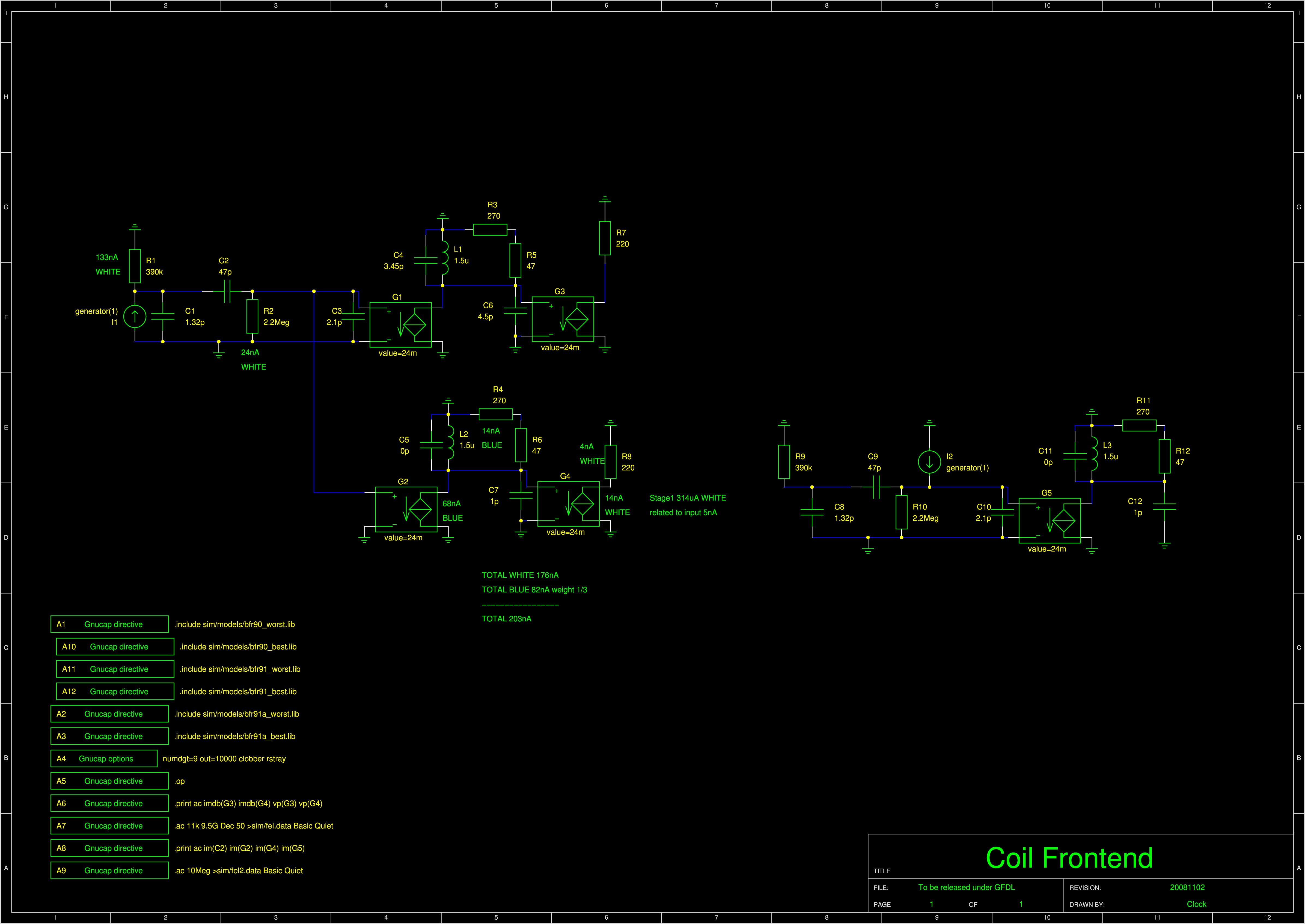
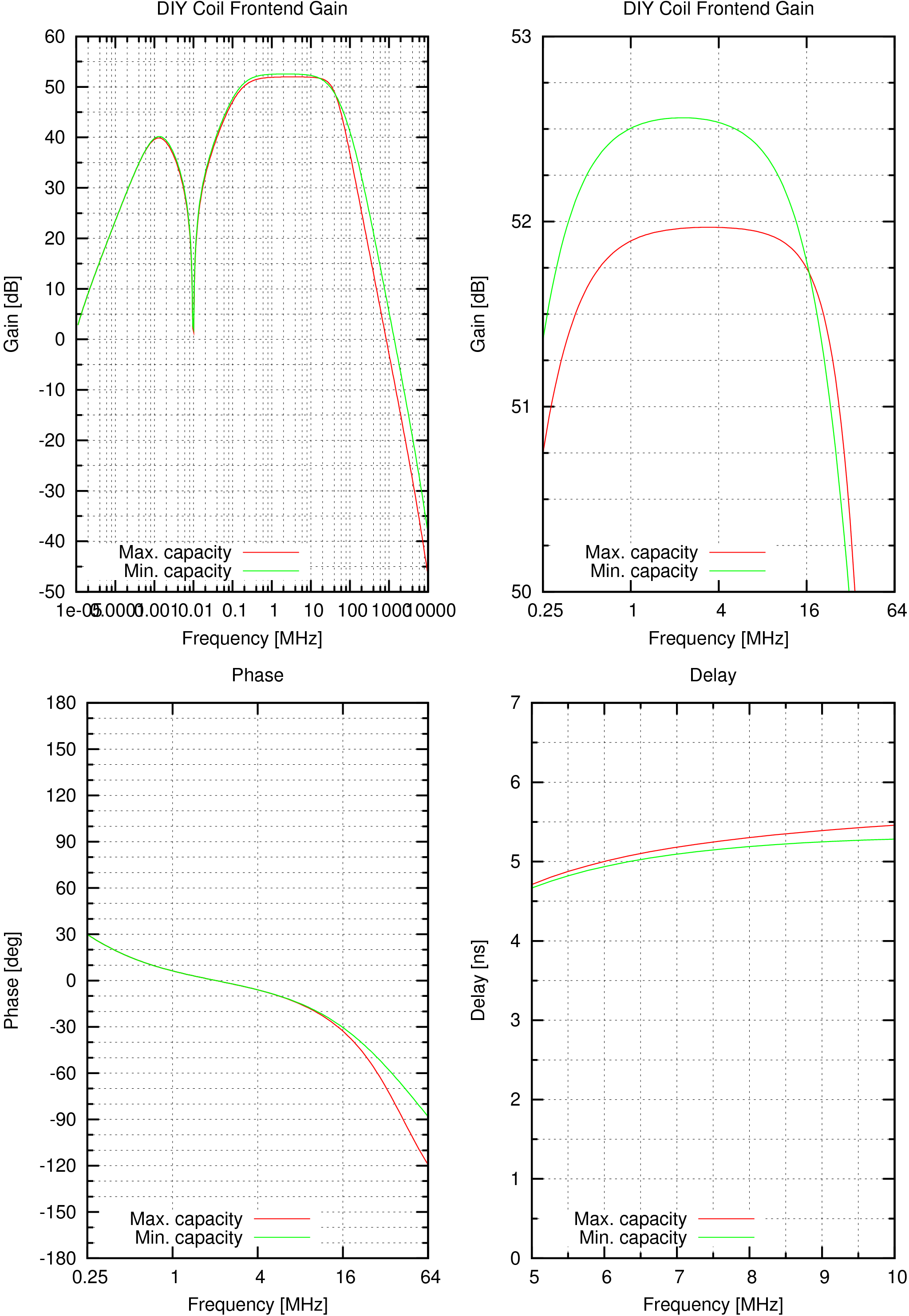
The problem is the derivator actually attenuates and it also produces a lot of noise What about using a different mechanism for the derivator? Let's try to put a coil into the drain of BF998. We have to be careful to avoid resonance of the coil where the coil has nearly zero impedance and doesn't produce any signal.
A coil with 180 ohm at 10 Mhz must have 2.9uH. The resonance should be a bit above 16 MHz because it will produce large attenuation there. It will help us to filter the high frequencies! :)
Bourns has 27 Mhz SRF min. with 6.8uH and Q at least 50. We have to simulate the biggest possible and smallest parallel capacity to the coil. The tetrode input is from 1.8pF (typ. BF960) to 4.5pF (BF960 max. datasheet from unknown manufacturer). Since the min. is often not guaranteed, let's assume 1pF. For the coil we assume 0pF because it may be high-quality hand-wound aircore. I don't know if ferrite produces noticeable Barkhausen noise, if it did, a handwound aircore would be necessary.
|
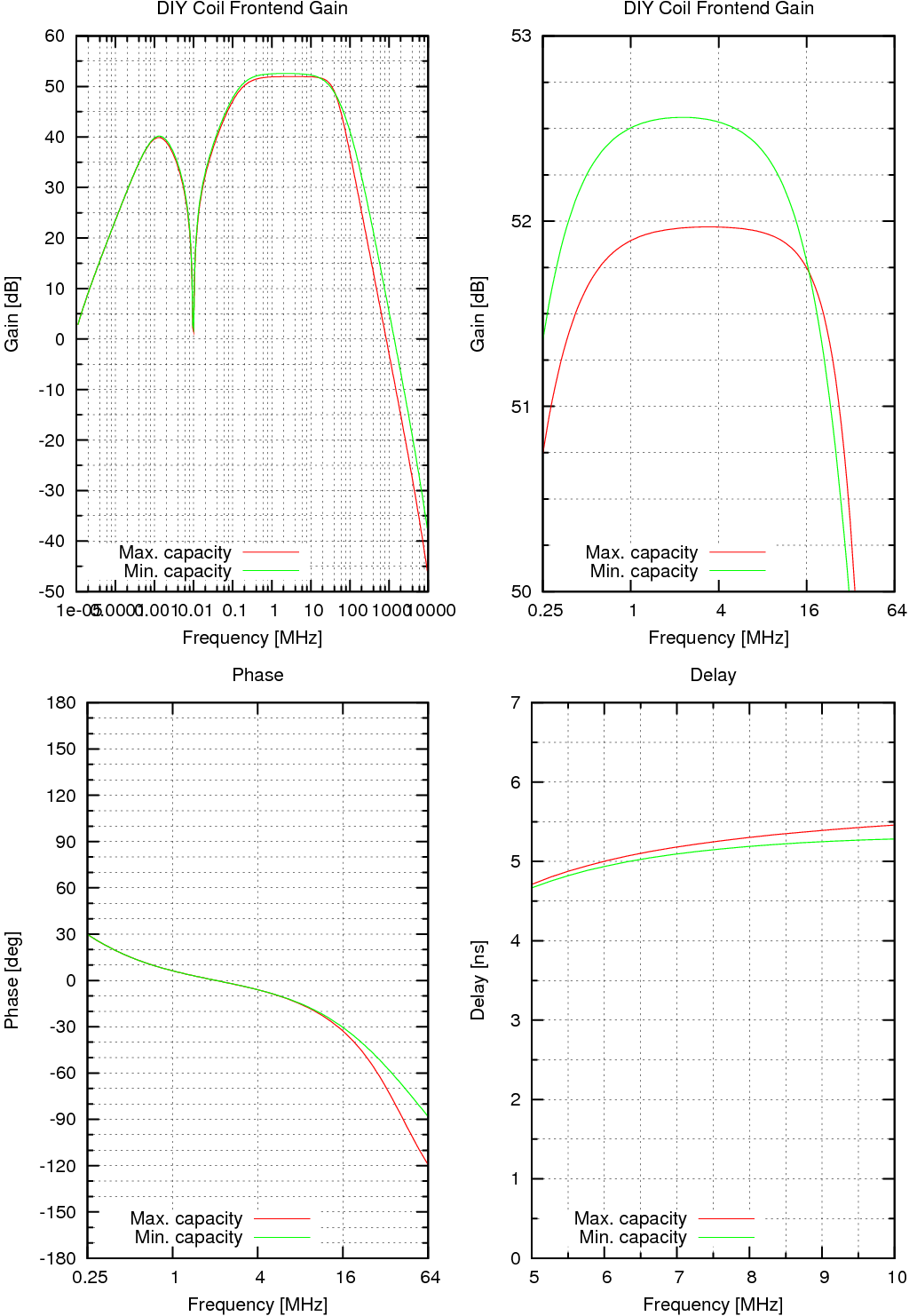
6.8uH is too aggressive. Let's try a smaller one: 3.3uH with 45 Mhz which according to the LC calculator gives 3.8pF. Still too aggressive let's try 2.7uH, 50 MHz, 3.75pF. Still too much, 2.2uH, 55 MHz, 3.8p. I aslo tried adding an additional 3pF capacitor to get less relative capacitance spread but have a feeling it doesn't really help. 1.8uH, 60 MHz, 3.9pF. 1.5uH, 70 MHz, 3.45 pF. 1.5uH makes my day! | |||||||||||||||||||||||||||||||||||
#Freq           im(C2)         im(G2)         im(G4)         im(G5)
 10.E+6         0.603567587    109.78308      239.327977     112.86639
|
There are sources of white and blue noise. The blue noise numbers increase with square of frequency. Since the lower frequency threshold is negligible in this respect, the blue noise contributes only 1/3 to the total noise energy. Therefore it is divided by 3 before added up to the white noise. We are getting 198nA of noise here. 0.2uA is what I measured in daylight lighting in a corner where you could just read. Midday overcast daylight gives 30uA when SFH203 is pointed towards the sky. According to Wikipedia this should be about 15,000 lux. Therefore the lighting equivalent to the amplifier noise is about 100 lux of daylight. If the 390k resistor were replaced by 100k as in the previous version, it would be 300 lux! Wikipedia says the recommended light for reading is 600 to 800 lux, the rough measurement seems to make sense. I will try making a coil from 0.8mm enameled wire. |
|
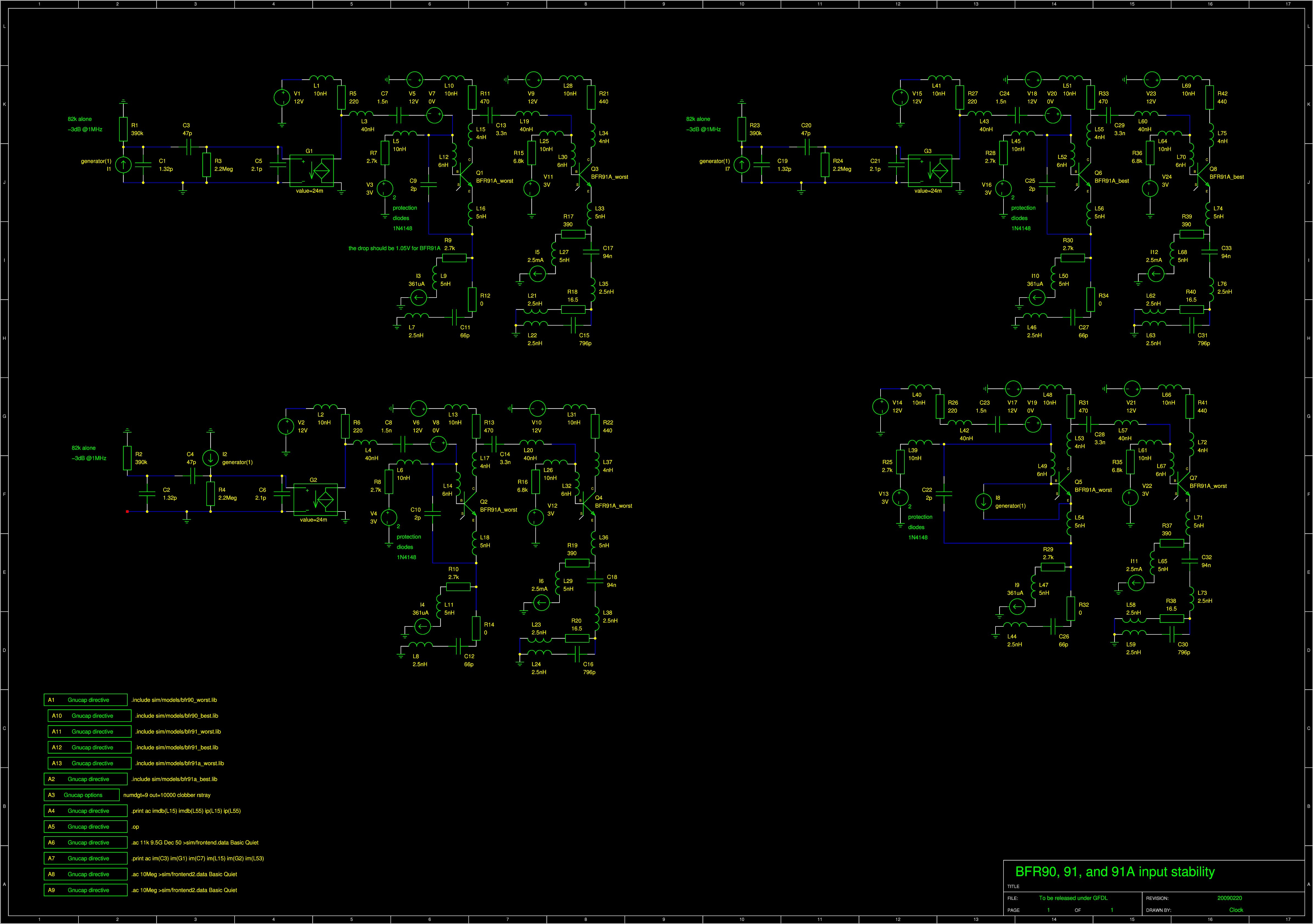
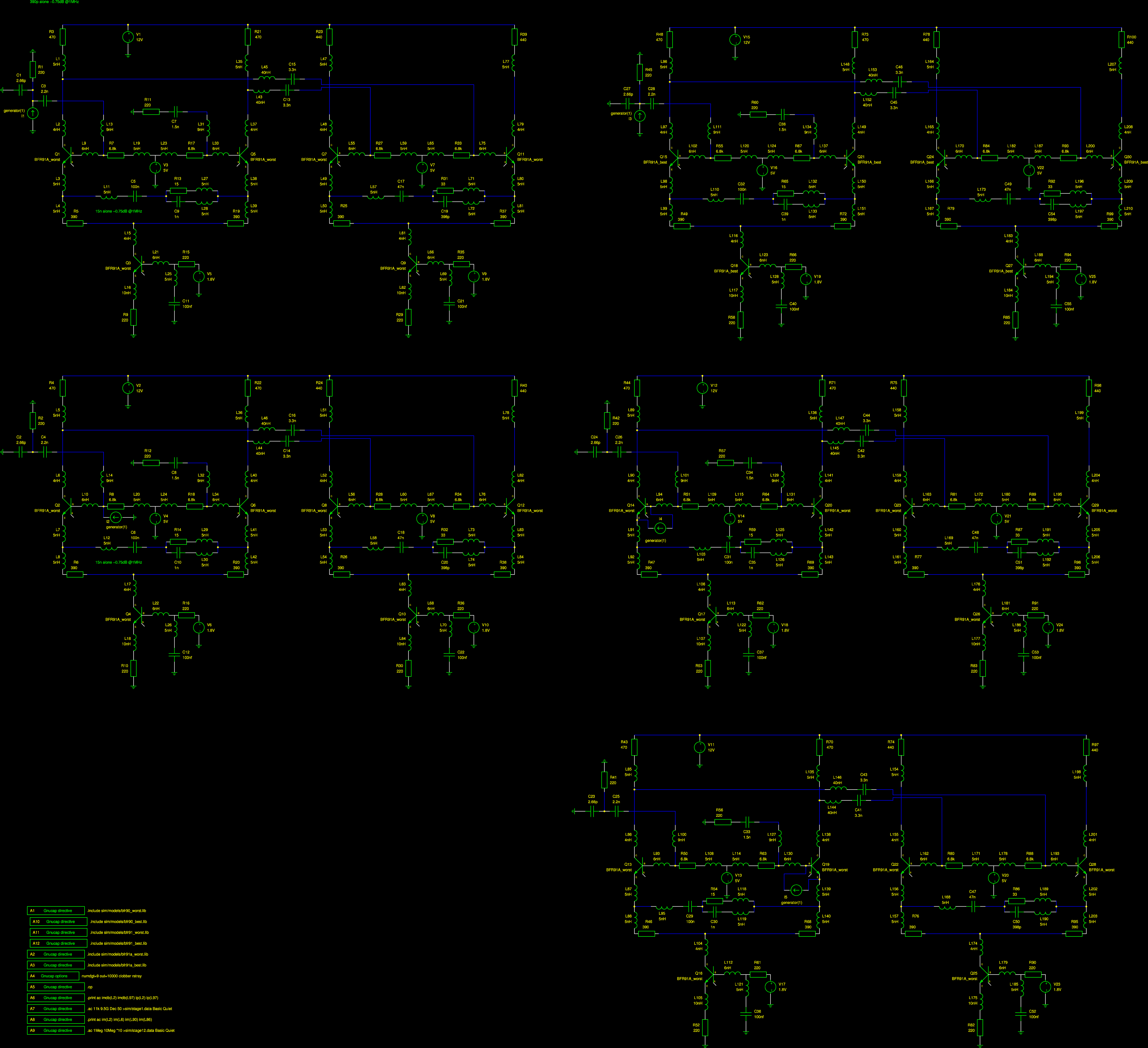
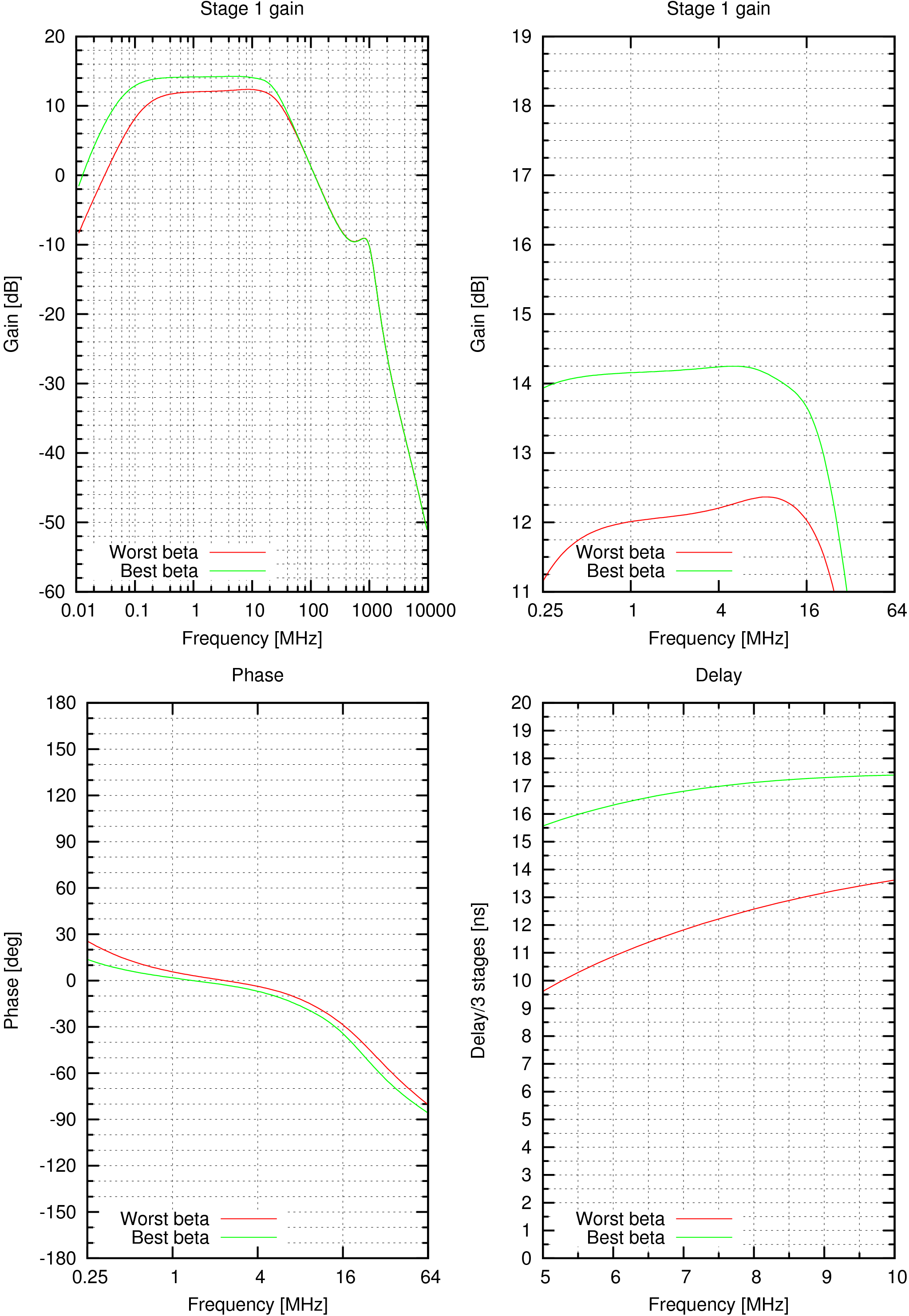
The 220 Ohm resistor in series with the current source base is for filtering the 1.8V voltage. The 2pF in each base had to be replaced for 2.66pF on the output because with the protection diodes in the base it oscillated. Originally the right base was blocked with 100nF but that causes an oscillation too. I symmetrized the input impedance and recalculated all the resistors and capacitors to match the bandwidth. The noise has to be recalculated too. | |||||||||||||||||||||||||||||||||||
#Freq           im(L2)         im(L6)         im(L90)        im(L86)
 1.E+6          3.9859296      4.20015545     4.81952084     4.0955076
 10.E+6         4.14447111     4.15099205     4.70087401     3.7647986
| Noise Source | If the unit current signal were injected into the input instead the noise source, how many times would the output amplitude be bigger @10MHz? | Equivalent shot noise DC current produced by the noise source | Equivalent shot noise DC current as if produced by the input @10MHz | Noise spectral character as if produced by the input | Total inband contribution (blue sources have weight 1/3, white ones 1/1) |
| 6k8 left | im(L2)/im(L6)=1 | 7.6uA | 7.6uA | white | 7.6uA |
| 6k8 right | im(L2)/im(L6)=1 | 7.6uA | 7.6uA | white | 7.6uA |
| 220 right | 1 | 236uA | 236uA | white | 236uA |
| base left | im(L2)/im(L90)=0.88 | 100uA | 129uA | white | 129uA |
| base right | im(L2)/im(L86)=1.1 | 100uA | 83uA | white | 83uA |
| collector left | im(L2)=4.14 | 2.5mA | 129uA | white | 129uA |
| collector right | im(L2)=4.14 | 2.5mA | 129uA | white | 129uA |
| TOTAL | 721uA | ||||
200 left is not counted because that's counted in the previous stage.
|
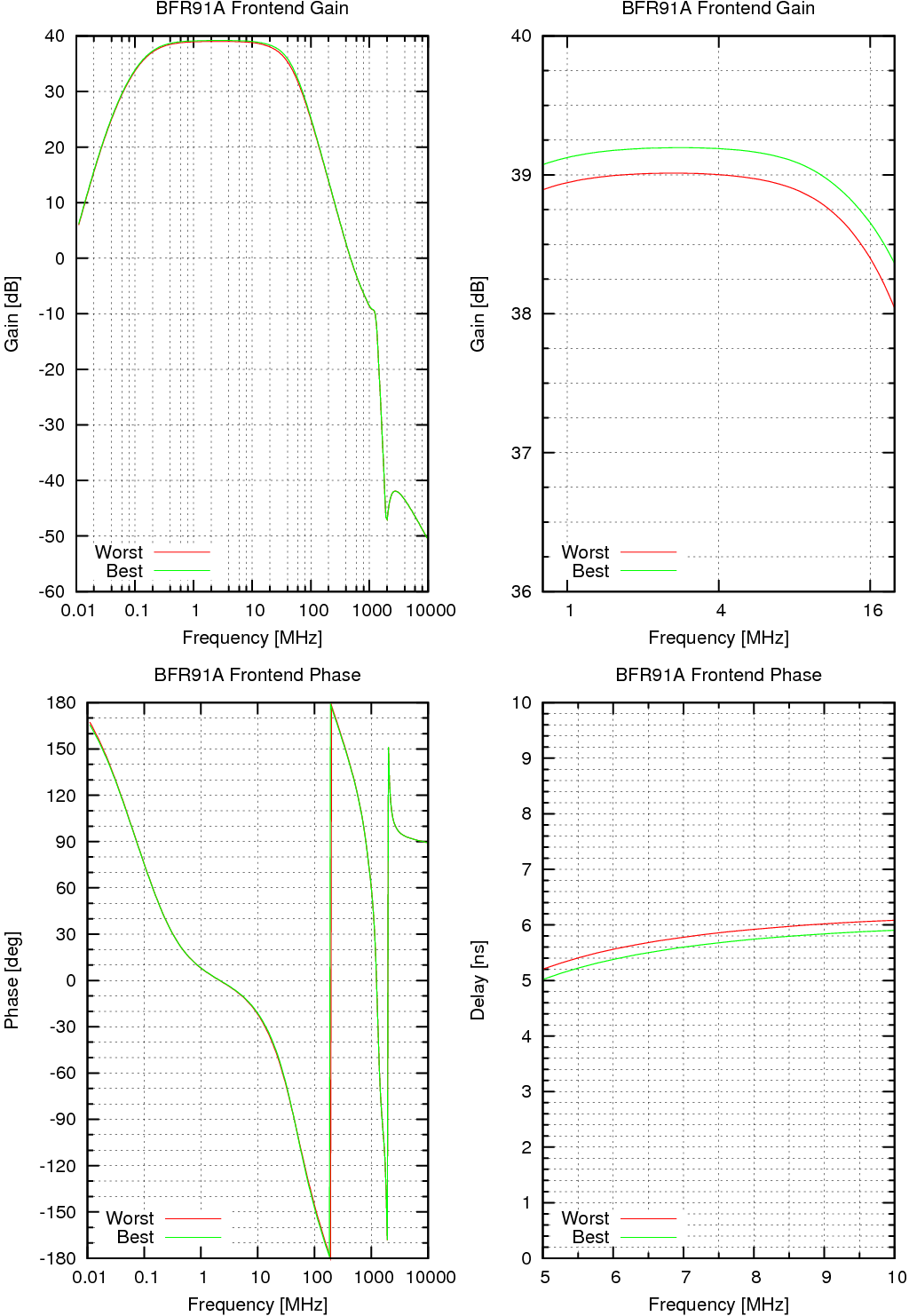
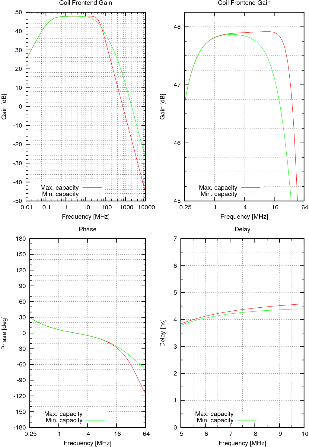
The upper part of the characteristic is tuned that -0.75dB relative to maximum is reached at 16MHz or higher for both curves. The lower part: alone, 390p decopuling and 1.5n emitter produce -0.75dB at 1MHz. Hard to say exactly, because it depends on the transistor gain. The aim is to increase them simultaneously until the jitter drops to 4ns/3 stages. This goal is set in the main limitter section. The values are rounded to the R6 series (1n 1.5n 2.2n 3.3n 4.7n 6.8n for example) because the R12 capacitors seems to be difficult to get from my experience. |
I tried to wind coils with 0.15mm diameter enamel wire on a ball point pen and a 14.7mm diameter (CD spindle) but it had apparently too much capacitance. The resonant frequency was like 13 MHz with an oscilloscope probe of unknown capacitive loading. 10,3 and 2.8uH. Then I tried 1mm^2 enamel on 16mm dia and got 3.65uH with self-capacitance of 9.5pF, with oscilloscope probe stating 8.0pF. That's only 1.5pF and it's excellent!
The next step is to double-wind a coil and take out the spacer between the turns and fixate the coil. Then measure in a setup without capacitive loading using impednace matched coaxial cable.
Double-winding showed to be impractical. The resulting winding with gaps was mechanically unstable. I abandoned that without measuring the inductance and resonance.
| Inner diameter | # turns | Wire dia. | Length | Inductance | Resonant freq. | Capacitance |
| 3xM5 plastic bolt | 20 | 0.3 mm | 16.3 mm | 1.66 uH | 105.6 MHz | 1.37 pF |
| 3xM5 plastic bolt | 35 | 0.3 mm | 28.3 mm | 2.63 uH | 90.9 MHz | 1.17pF |
| 14.7 mm | ca. 11 | 0.15mm | tightly packed | 2.9 uH | 63.0 MHz | 2.2 pF |
| 8 mm | ? | 0.15mm | tightly packed | 10.45 uH | 41.4 MHz | 1.43 pF |
| 16.0 mm | 20 | 1.0mm | ca. 22 mm (unstable) | 3.65 uH | 64.2 MHz | 1.68 pF |
The best coils insofra seems to be the 35 turn one. It is mechanically precisely shaped. I estimate the inductance needed to be somewhat less than twice 1.5uH because the capacitance of the coil is small and doesn't change from piece to piece. The coil.
I calculated the BF908 input impedance From the BF908 datasheet complex reflection coefficient gamma using formula Zin=Z0*(1+gamma)/(1-gamma). At 50MHz at 15mA DC current it came out 25Ohm -1122iOhm. That means the internal resistance in series with the gate capacitor is 25 Ohm.
|
The 2.63uH inductor resonates with the 100nF blocking capacitor at 310kHz which could influences the frequency response. Therefore the 220 Ohm resistor and 100nF capacitor were added into the characteristic simulation. It can hardly influence the noise since 100nF has reactance of 1.6 Ohm at 1 MHz the lower band edge and 0.16 Ohm at 10MHz. Therefore it destroys most of the current noise from the 180Ohm and it noises only like a 2.2 MOhm resistor at 1MHz. This causes unacceptable frontend gain of 90dB for 10kHz. Without simulating the second 47pF the blocking seemingly needs a huge cap of 1mF. Therefore I added also the second 47uF to simulate the LF response. Then I reduced the blocking cap to 100uF so it doesn't boot up too long and the cap is not too big physically. The dynamic range for low frequencies of the 1st MOSFET will not be worse for low blocking capacitance than the old RX because the old RX had there 22 Ohm as well even bigger value. If the capacitance is not sufficient the signal effectively builds up on the power limiting resistor 220 Ohm. Will 100uF suffice to protect against saturation by 100Hz lighting signal? The current gain is 25dB that's 17.7 times. Driving 220 Ohm resistor at the end it makes a transimpedance of 3.9k. Even if the street lamp drove the PIN into total cutoff (50V/390k=128uA), the voltage would be just 500mVpp at the output of the second stage! The voltage on the PIN would be 50 Volt at that moment! The resonance of the 100nF (with 6nH 6MHz) doesn't have to be simulated because it goes into short circuit - an ideal behaviour we need | |||||||||||||||||||||||||||||||||||
|
The factory made RX would have 1.5% less range than handmade coil if there were no Barkhausen Noise! Richard Clarke from University of Surrey UK said:
I have not yet heard of anyone having a problem with Barkhausen.
I can't think why ferrite should be worse from that point of view
than any other ferromagnetic material.  Says Giles -

   "The frequency range of Barkausen emissions is
    usually 10-500 kHz ..."
500kHz is inband because the lowpass filter is extended to avoid excessive delay between 5MHz and 10MHz frequencies. Therefore Barkhausen noise may be a problem. |
#Freq           im(G4)         im(G11)        im(G10)        im(G7)         im(G3)
 1.E+6          430.941808     443.060655     0.0950952065   0.396484203    1.08690789E+3
 10.E+6         423.506489     435.400869     0.878702198    3.85777629     109.77995
| Noise Source | If the unit current signal were injected into the input instead the noise source, how many times would the output amplitude be bigger @10MHz? | Equivalent shot noise DC current produced by the noise source | Equivalent shot noise DC current as if produced by the input @10MHz | Noise spectral character as if produced by the input | Total inband contribution (blue sources have weight 1/3, white ones 1/1) |
| Photodiode dark current | 1 | 5nA | 5nA | white | 5nA |
| 390k | 1 | 133nA | 133nA | white | 133nA |
| 2.2M | im(G4)/im(G11)=0.97 | 23.6nA | 25nA | white | 25nA |
| 25 Ohm | im(G4)/im(G10)=482 | 2.08mA | 9nA | blue | 3nA |
| 470 Ohm | im(G4)/im(G7)=109.8 | 11uA | 0.9nA | blue | 0.3nA |
| First MOSFET | im(G3)=109.8 | 840uA | 69.7nA | blue | 23nA |
| Second MOSFET | im(G4)=423.5 | 840uA | 4.7nA | blue | 1.6nA |
| 220 Ohm | im(G4)=423.5 | 236uA | 1.3nA | white | 1.3nA |
| Stage 1 | im(G4)=423.5 | 721uA | 4nA | white | 4nA |
| Total | 196.2nA | ||||
If we calculate the noise figure for combined input impedance of 390k and 2.2M then it is 0.87dB!
The old receiver hat 650nA. The new one has 196.2nA. The ratio is 3.31, 4th root is 1.35, therefore we have 35% more range in darkness!
The noise is calculated for 300K or 26.85 degC. How much is it for -30 degC and 70degC? That's 243.15 and 343.15K. Almost all noise is resistive. That constitutes range increase of 5% and decrease of 3.3%

 Contact, support: Clock
on the Internet Relay Chat.© 1998-2016 Karel ‘Clock’ Kulhavý et al..
Contact, support: Clock
on the Internet Relay Chat.© 1998-2016 Karel ‘Clock’ Kulhavý et al.. 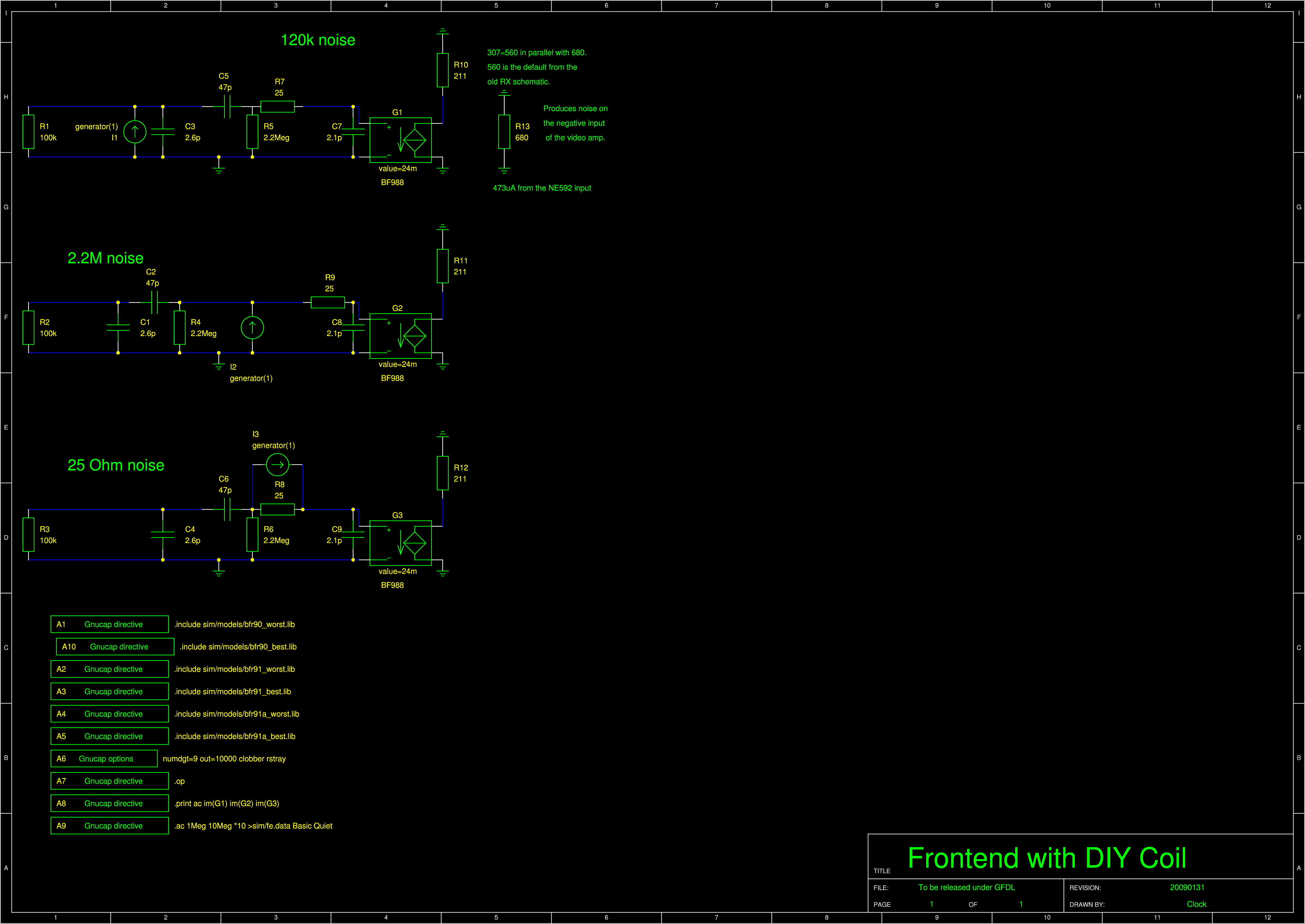
