|
Source: Siemenes Cross Reference Guide 1998 on datasheetarchive.com search for BFR90.
Since the model is from Philips, we assume the BF of 102 in the model corresponds to 90, so we should put there 45.3 and 340, respectively. Let's calculate the worst and best SPICE BF for BFR90 and the balancing resistors:
The model is from Motorola but we have only one typical value of 50 so it's clear. The BF in the model is 101 so the corresponding worst and best values are 50.5 and 505, respectively. Let's calculate the worst and best SPICE BF for BFR91 and the balancing resistors:
The model is from Motorola but we have only one typical value of 50 so it's clear. The BF in the model is 101 so the corresponding worst and best values are 50.5 and 505, respectively. | |||||||||||||||||||||||||||||||||||||||||||||||||||||||||||||||||||||||||||||||||||||||||||
|
The beta range of BFR91A is 40-300 which is 1:7.5, offset voltage 52mV, for 1:20 imbalance we need 1.05V on a resistor, with 2.5mA it's 420 ohm, closest standard value is 390. The beta range of BFR90 and 91 is 1:10 which is offset of 60mV. For imbalance 1:20 we need 1.2 V voltage drop at 2.5mA which is 470 Ohm. The available tuning values for the emitter in single sided simulation are: |
|
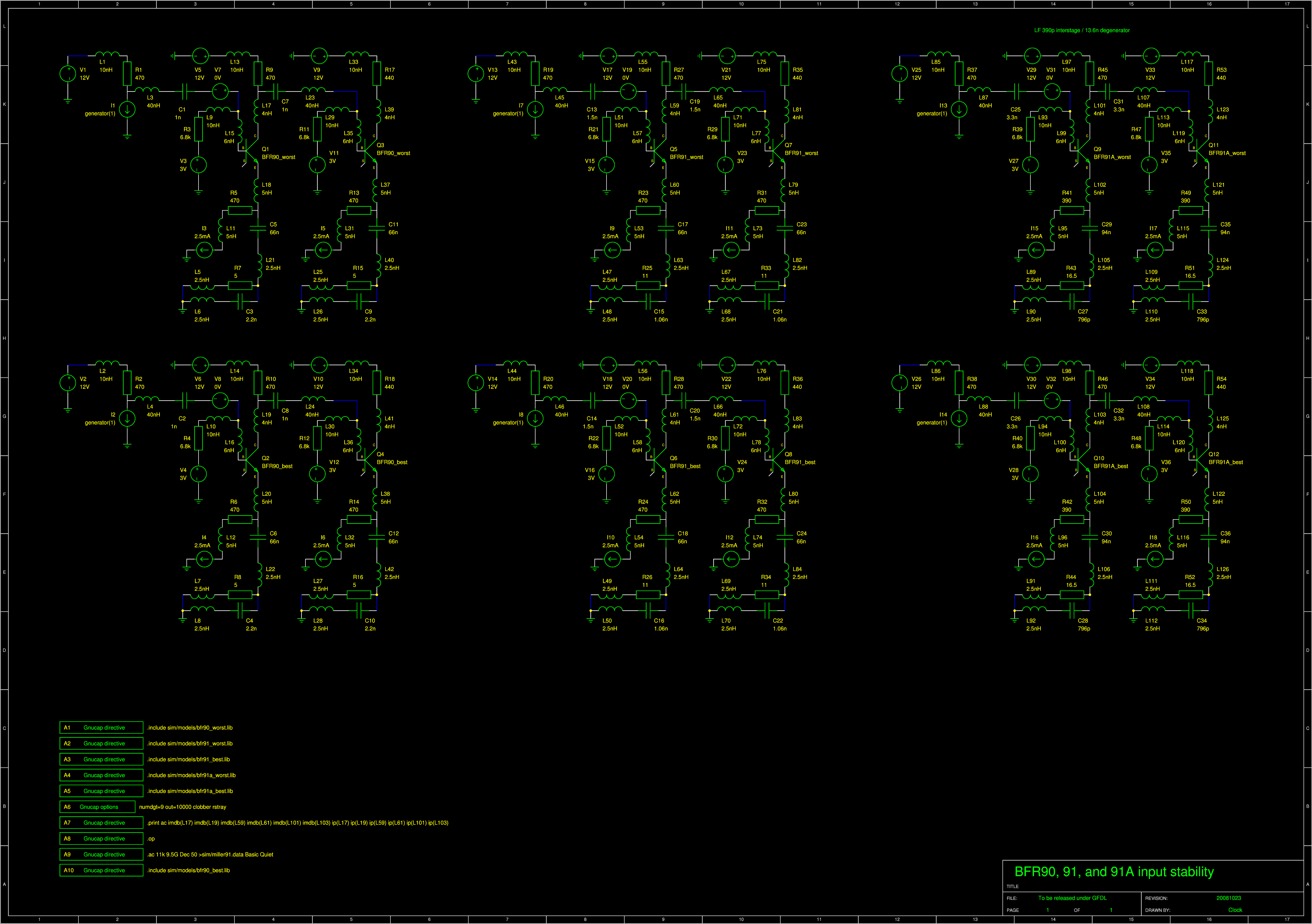
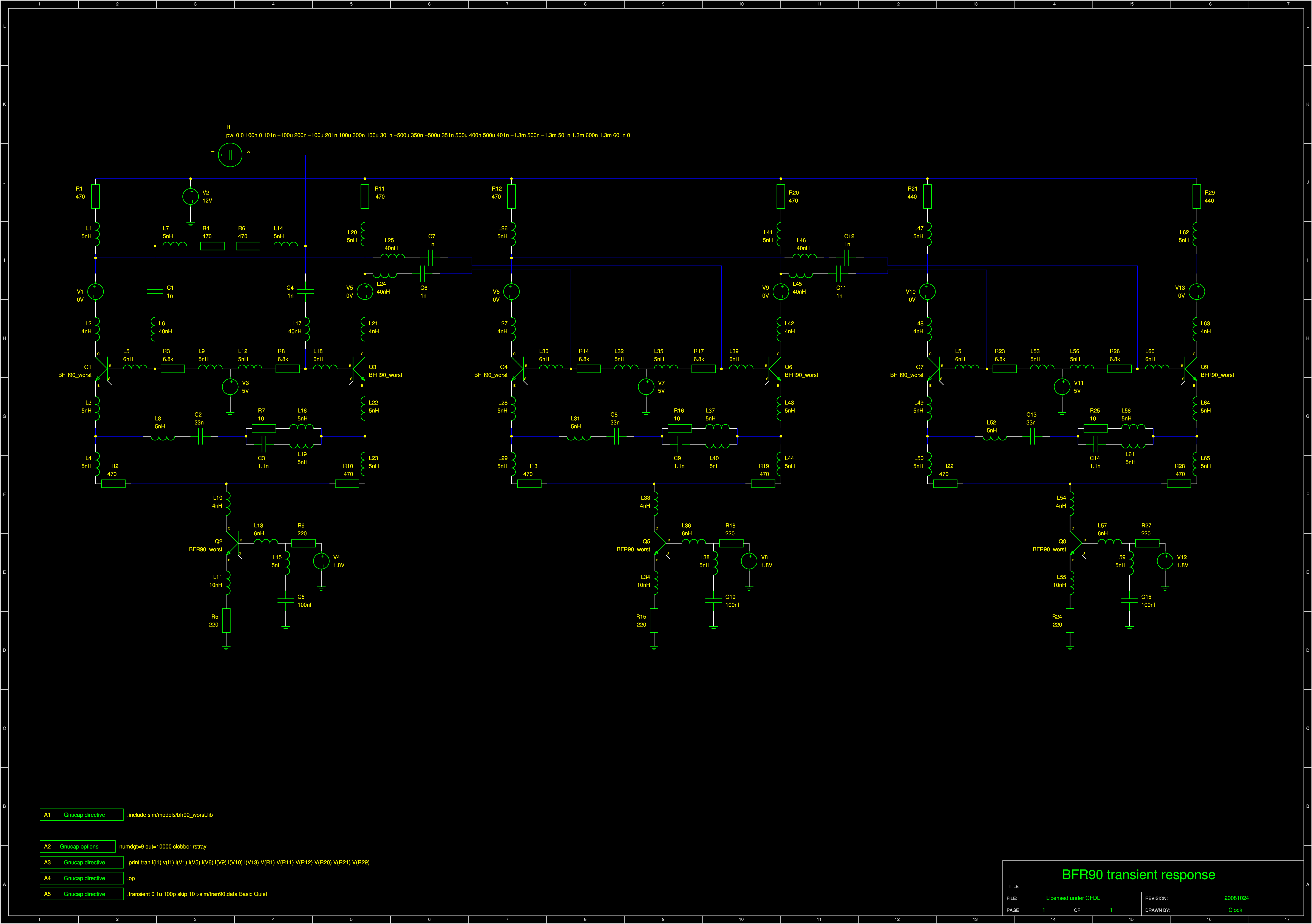
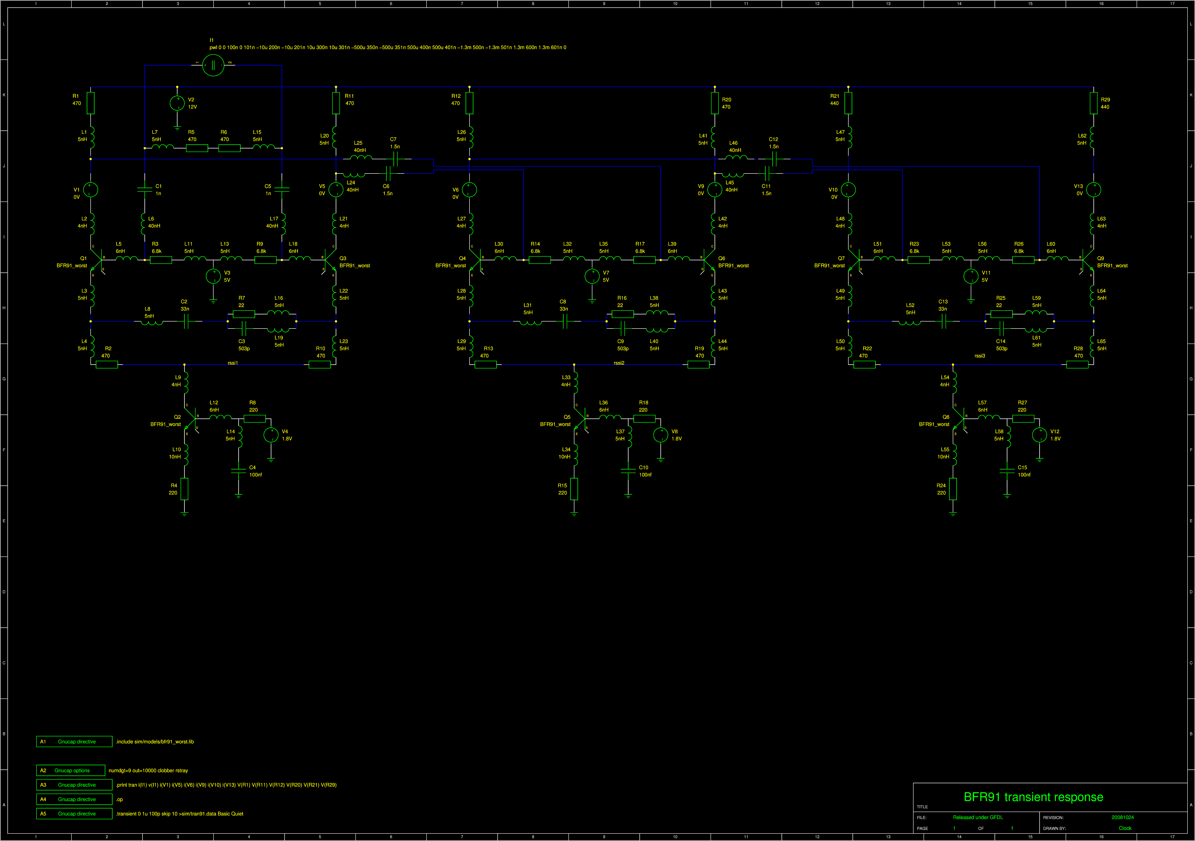
I added thte second stage is added to get a more precise impedance of the collector load. This affects the Miller effect. TO get -0.7d5dB drop at 1MHz one would have to use about 330 or 470p coupling capacitors. However this creates a deterministic jitter 7ns that's too much. So I put 1n there that's a compromise between LF rejection and jitter - now 4ns. The RC degenerator can be connected two ways. Small RC in parallel and big C in series to this. Or small R in series with big C and small C in parallel to it. If you tune both to have a -0.75dB cutoff at 1MHz, the latter causes high frequency deformation, whereas the former doesn't. So I selected the former one of course! The coupling capacitor alone has to be 390pF to get roughly 1MHz cutoff at -0.75dB. The big one in the emitter degenerator for BFR91A has to be 12nF. I took these 2 values and increased them both at the same time to get the new cutoff. Unfortunately the deteministic jitter was then 6.5ns so I increased the bandwidth downwards to get less jitter of 4ns. | |||||||||||||||||||||||||||||||||||
These are real components that will be in the real circuit.
| Transistor | Coupling Capacitor | Simulated LF Capacitor | Simulated HF Capacitor | Simulated Resistor | Real LF Capacitor | Real HF Capacitor | Real Gain Resistor | Real Balancer Resistor |
| BFR90 | 1n | 66n | 2.2n | 5 | 33n | 1.1n (1n+100p) | 10 | 470 |
| BFR91 | 1.5n | 66n | 1.06n | 11 | 33n | 503p (470p+33p) | 22 | 470 |
| BFR91A | 3.3n | 94n | 796p | 16.5 | 47n | 398p (330p+68p) | 33 | 390 |
|
|
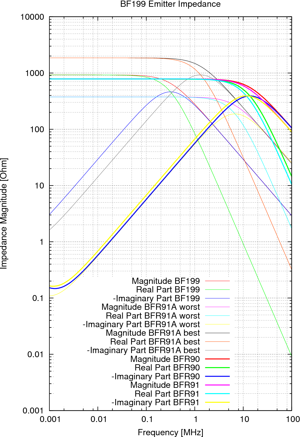
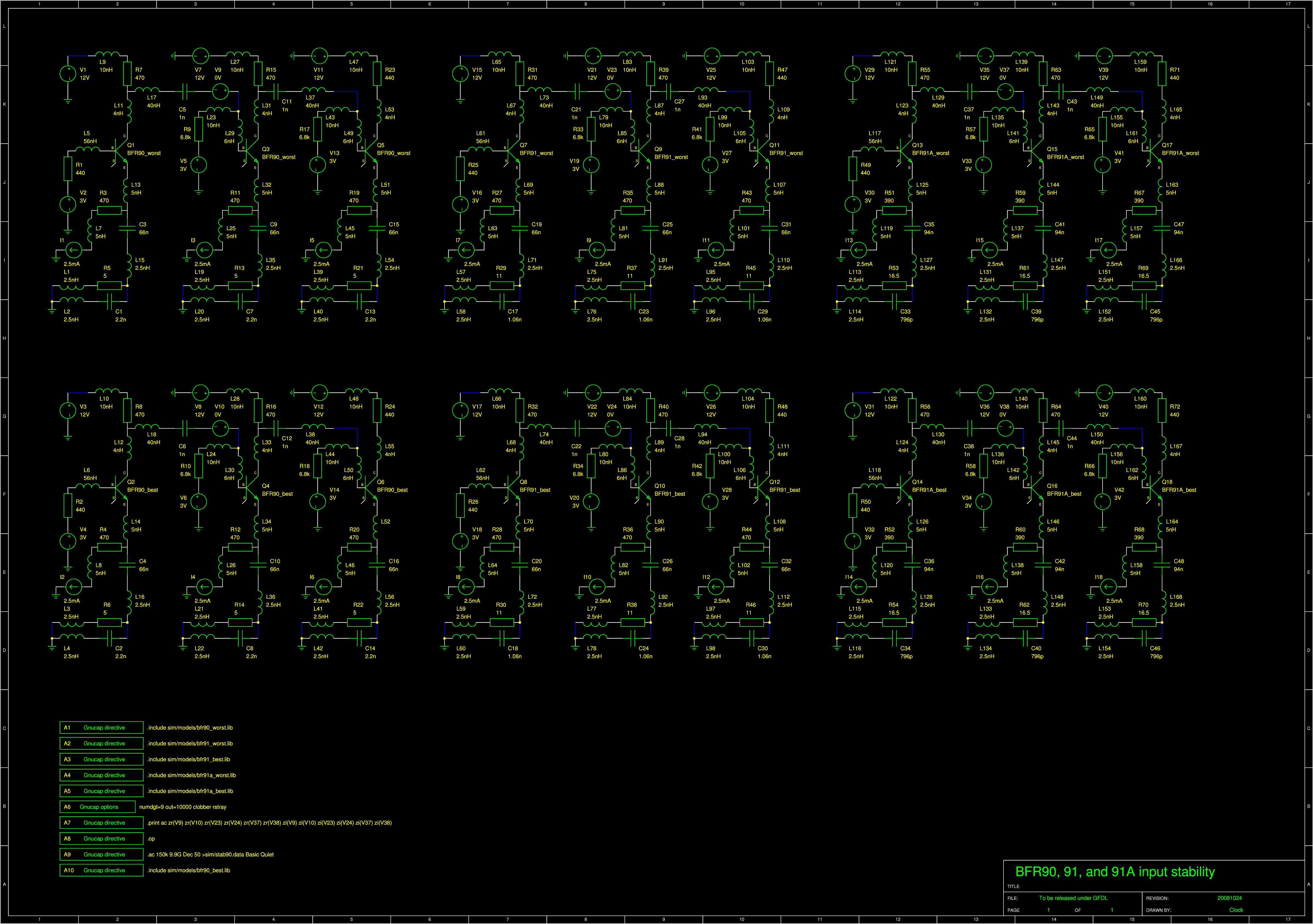
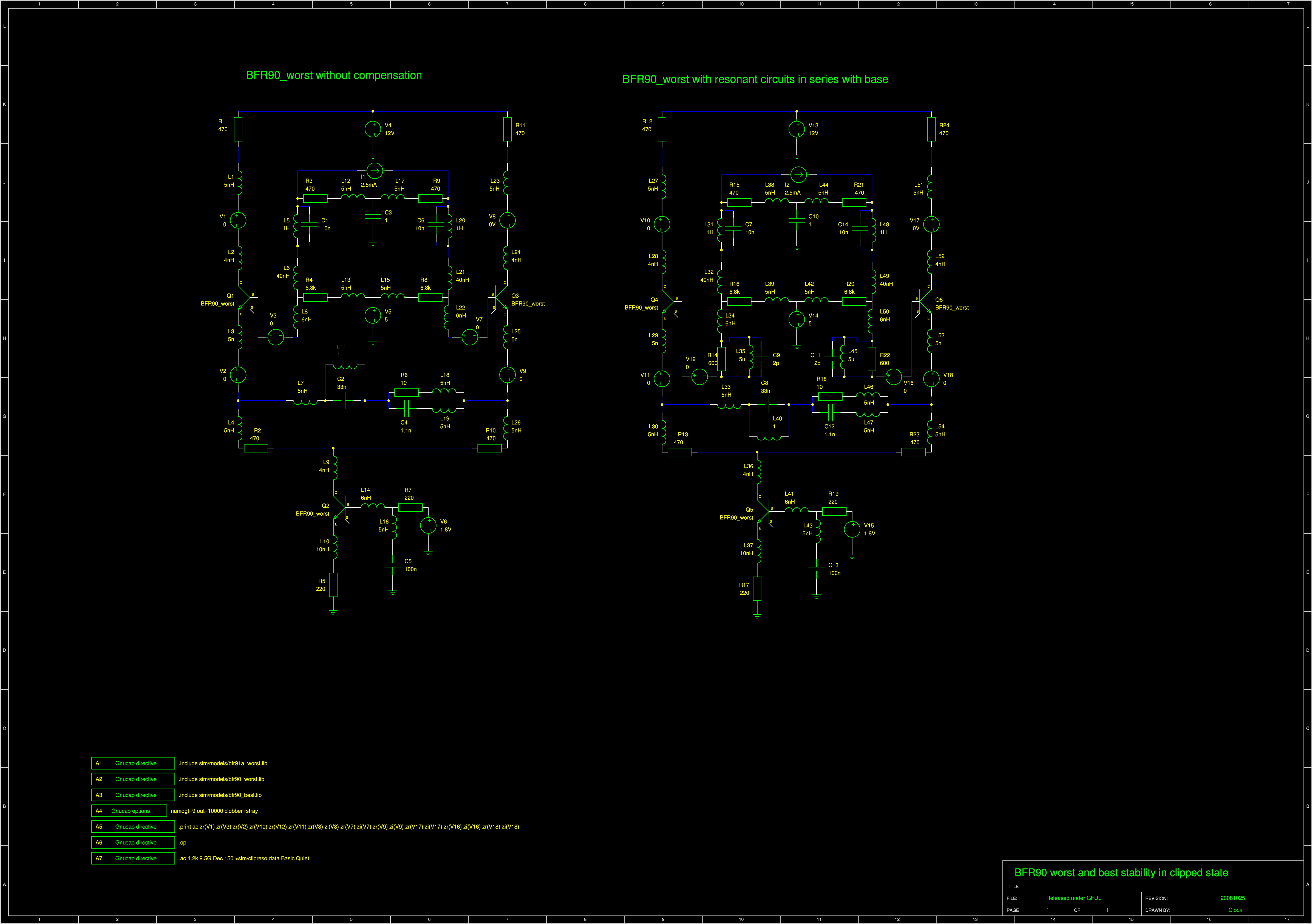
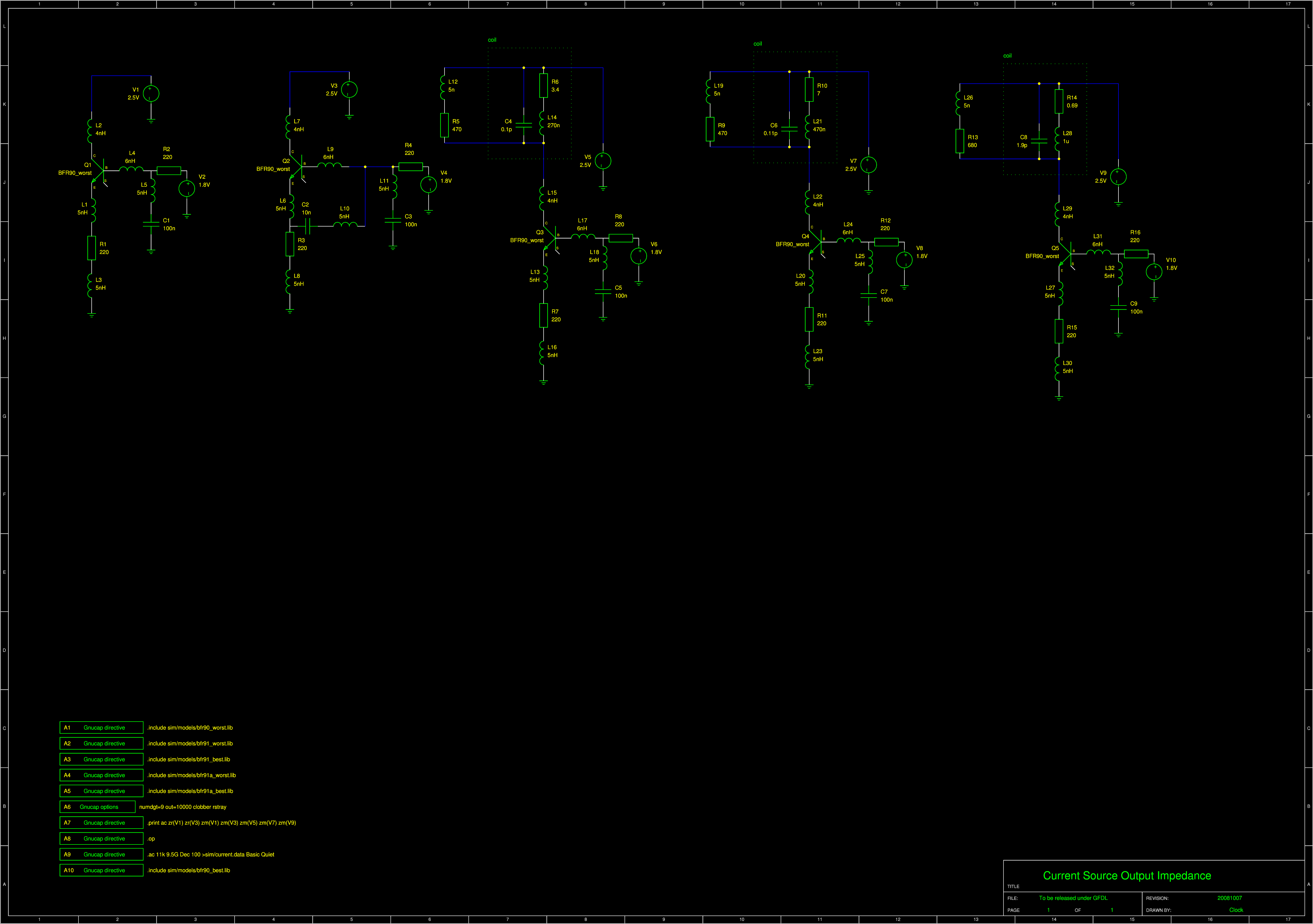
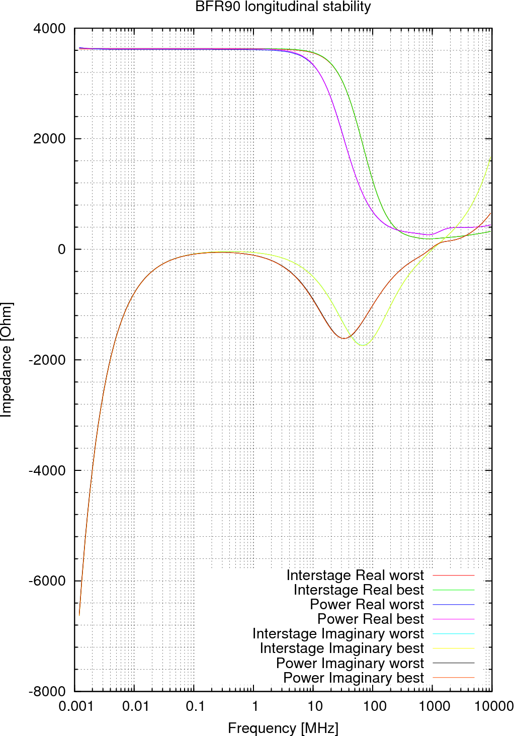
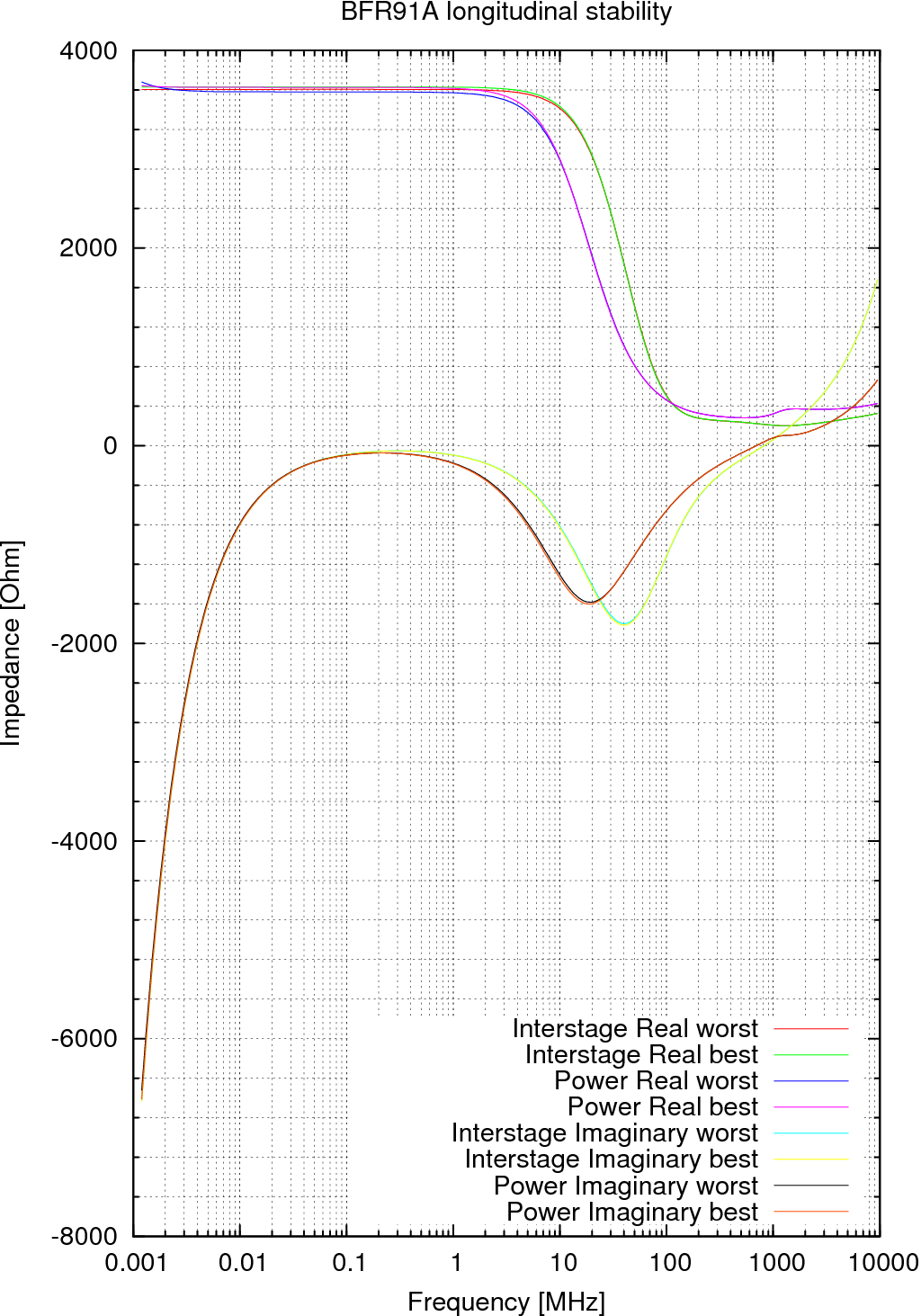
I am measuring the impedance seen between 1st and 2nd stage of a 3-stage amplifier. There are 3 stages to get an accurate result. The 1st stage is to simulate the capacitance of the collector. The 3rd is to simulate the influence of the input capacitance on miller effect and therefore also input capacitance of the 2nd stage. According to Experiment About Resistors, ordinary resistors (carbon film or metal film) have high series inductance. Therefore we need to use SMD reistors. I will simulate the inductance by the formula 1nH/mm and 40mm of wire length connecting two stages. I don't have a resistor ESL value but a 2mm long capacitor has 0.9nH (from this table) so let's assume the resistor conducts in a thinner layer and will have maybe some leads so let's give it 5nH. Let's assume ceramic disc capacitors with ESL of 2.6nH when soldered with leads as short as possible (as seen in the Murata document) and give it also 5nH for somewhat longer leads. The original model for the BFR90 and 91 transistors includes about 0 nH on collector, 1 on emitter and 2 on base. That suggests it's a model without the case. The transistor has 5mm shortest lead. Let's assume we can trim it down to 4mm without overheating that's 4nH more, that is 4nH collector, 5nH emitter and 6nH base. :) | |||||||||||||||||||||||||||||||||||
|
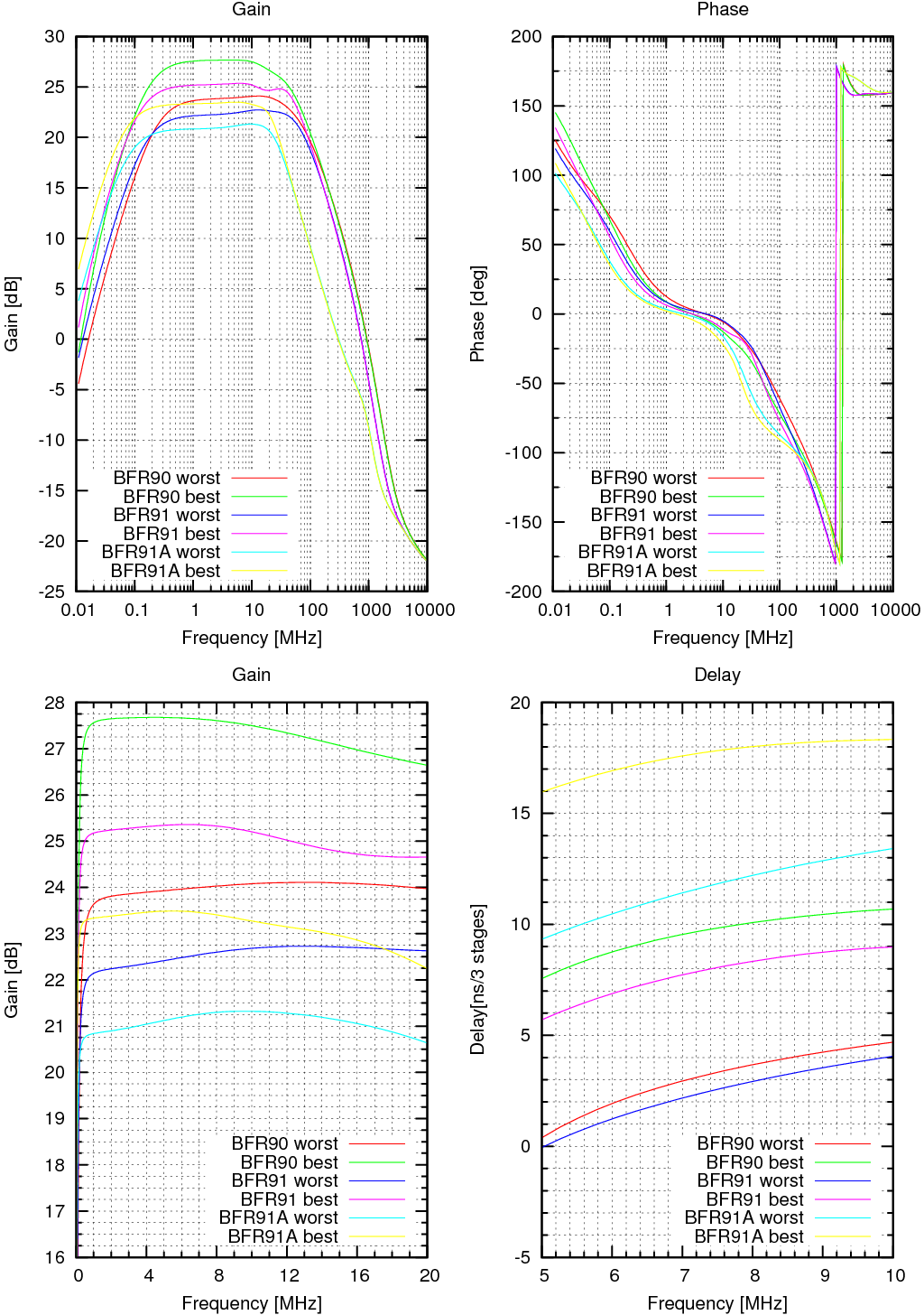
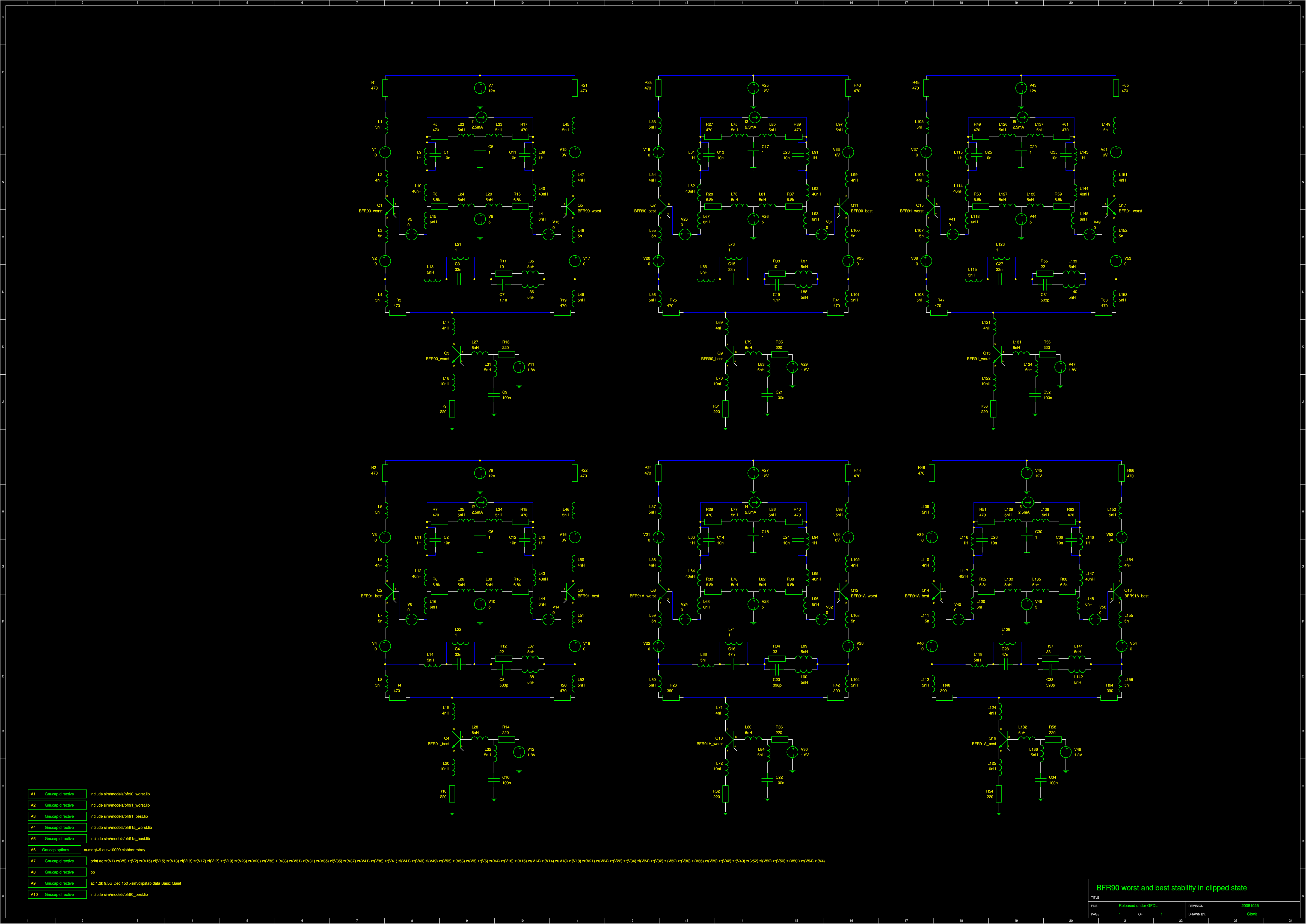
It's stable! :) |
|
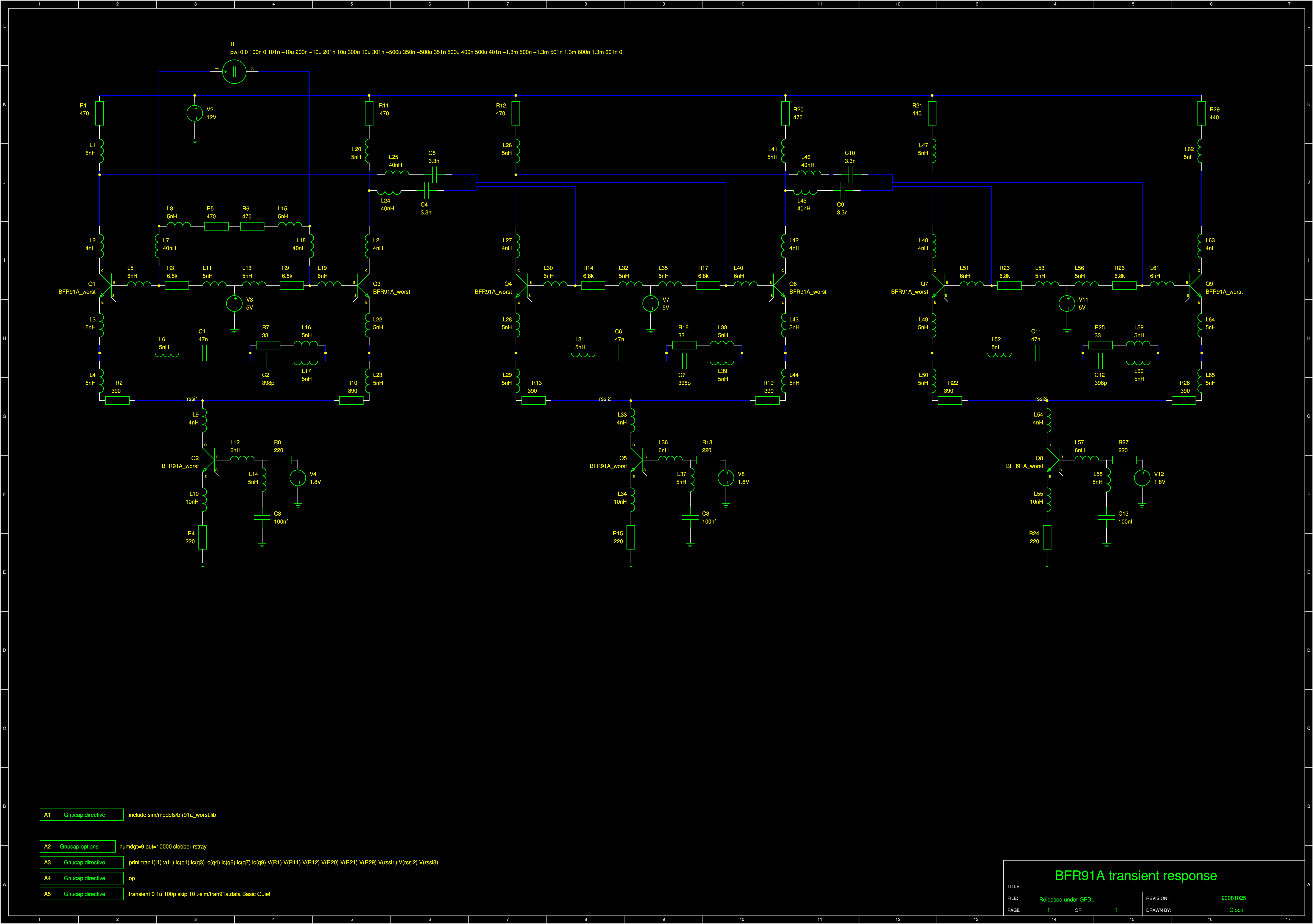
Why is the bias voltage 1.8V and 5V? 1.8V-0.7V is 1.1V to get precise current even if the E-B voltage of the current source varies from piece to piece. The current source is supposed to have collector voltage of 2.5V to get extra 0.7V against base to prevent closing in on saturation. 2.5mA times 470 is 1.175V we're at 3.675. Another 0.7V for E-B gives us 4.375. Now the minimum beta of the transistor is 25 which makes 100 microamp base current, times 6.8k is 0.68V. We're at 5.055 volt so we can use the 5V regulator conveniently! :) | |||||||||||||||||||||||||||||||||||
|
|
|
| |||||||||||||||||||||||||||||||||||
|
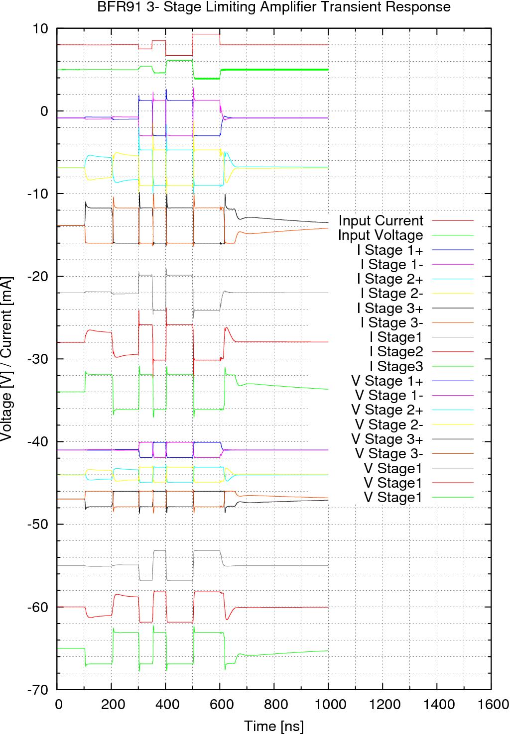
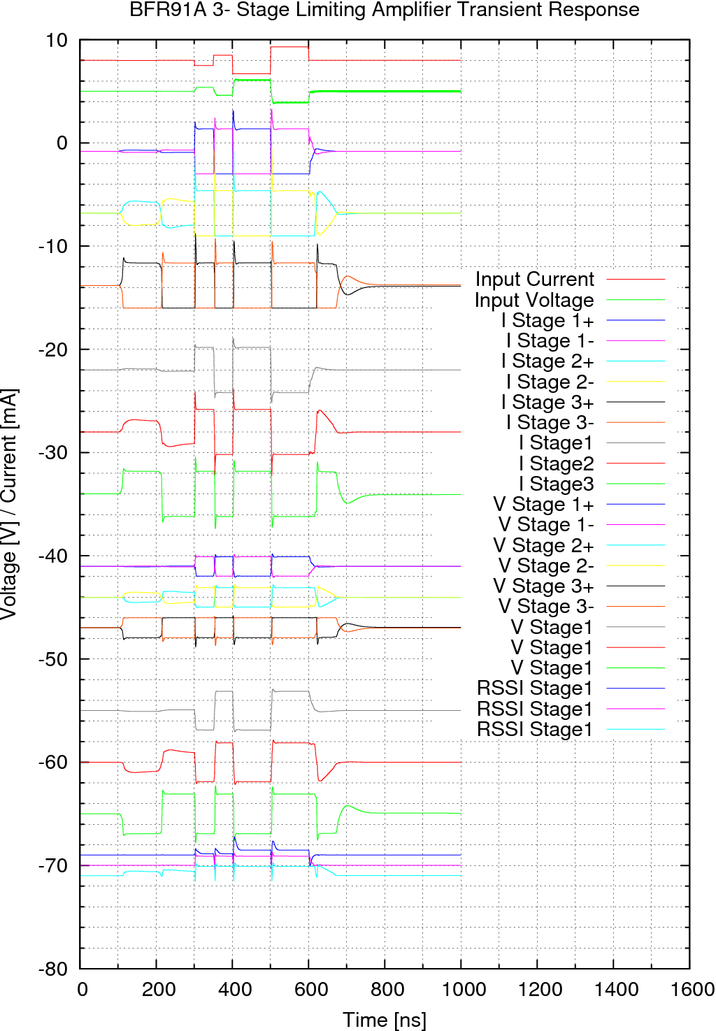
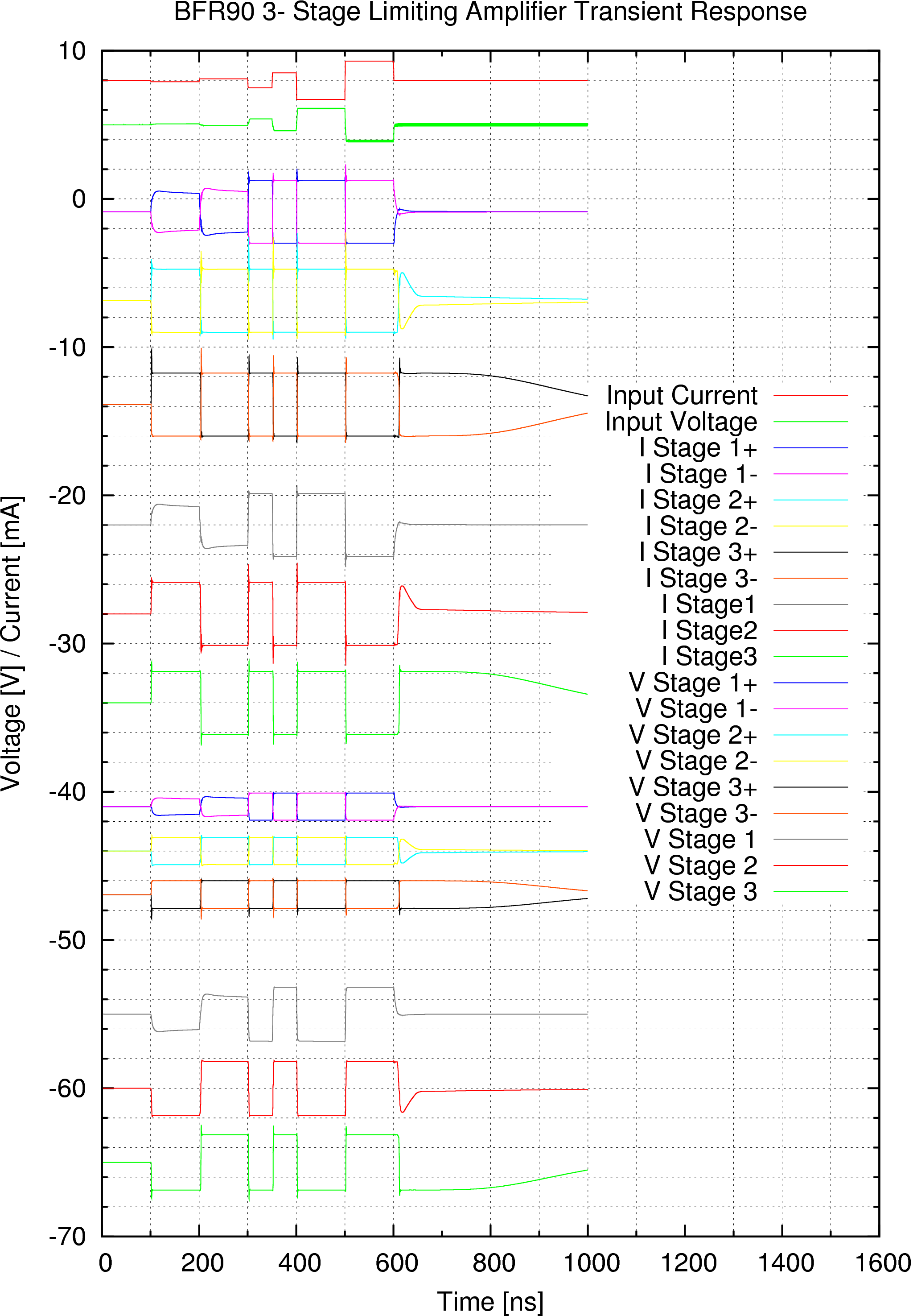
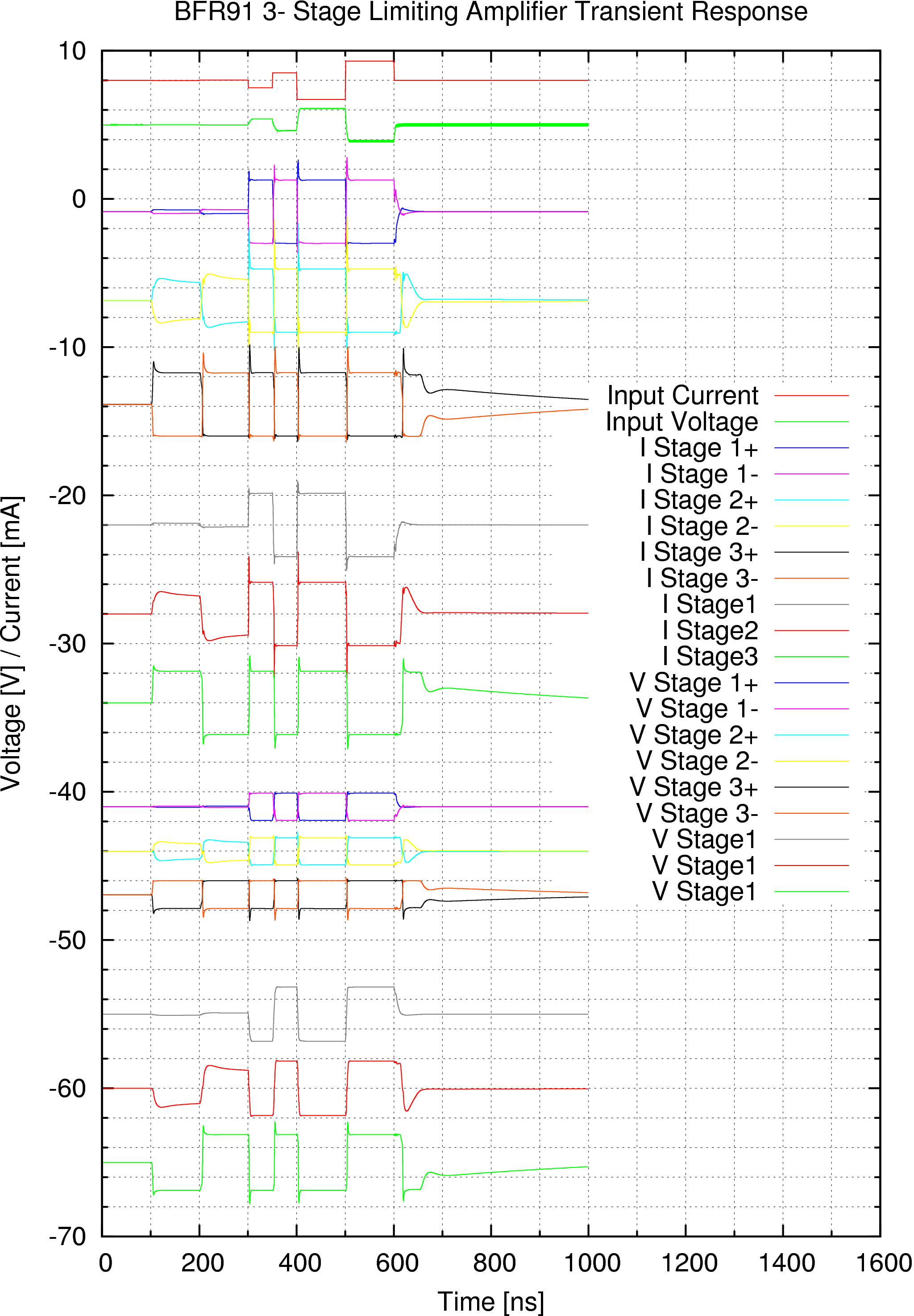
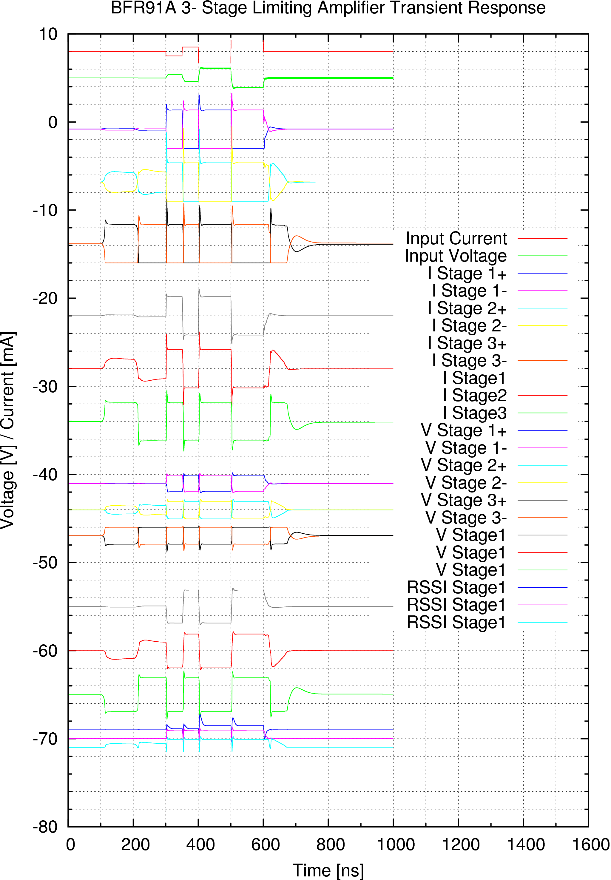
We see sometimes there is a glitch on the voltage if the limitter is not limitting. At the end we are going to take only one half of the signal. The glitches are not present if the amplifier goes into full limitation. That means we have to construct the amplifier in a way that it limits even the weakest signal. Also we have a unilateral spikes on the output signal. I wouldn't send them into the coaxial. What if they cause unpredictable reflections? What if they radiate out of the coaxial and cause RFI? I would send then into a HC04 and tie few HC04's together and use them as a coax driver. It also saves supply current! |
|
| |||||||||||||||||||||||||||||||||||
|
|
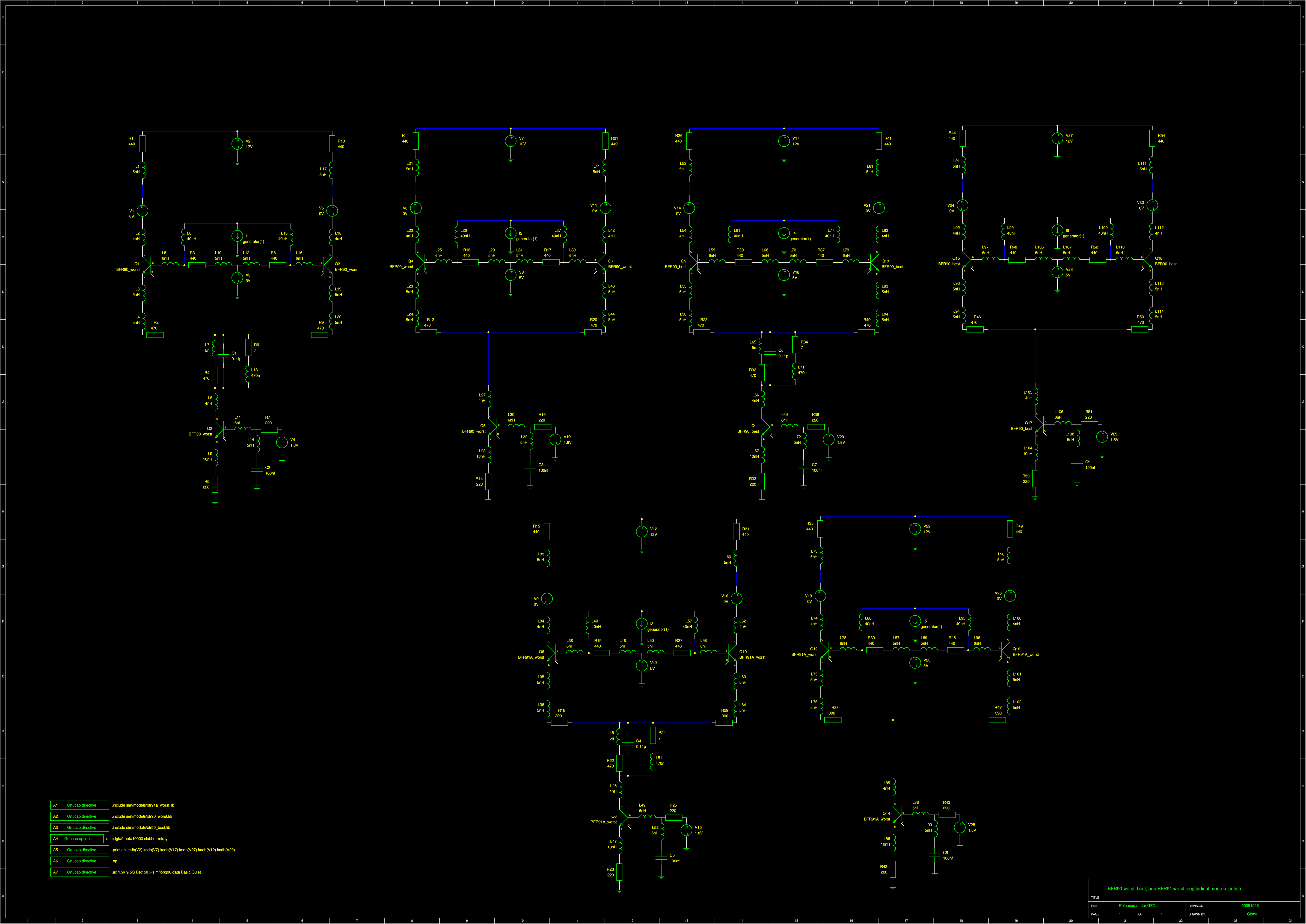
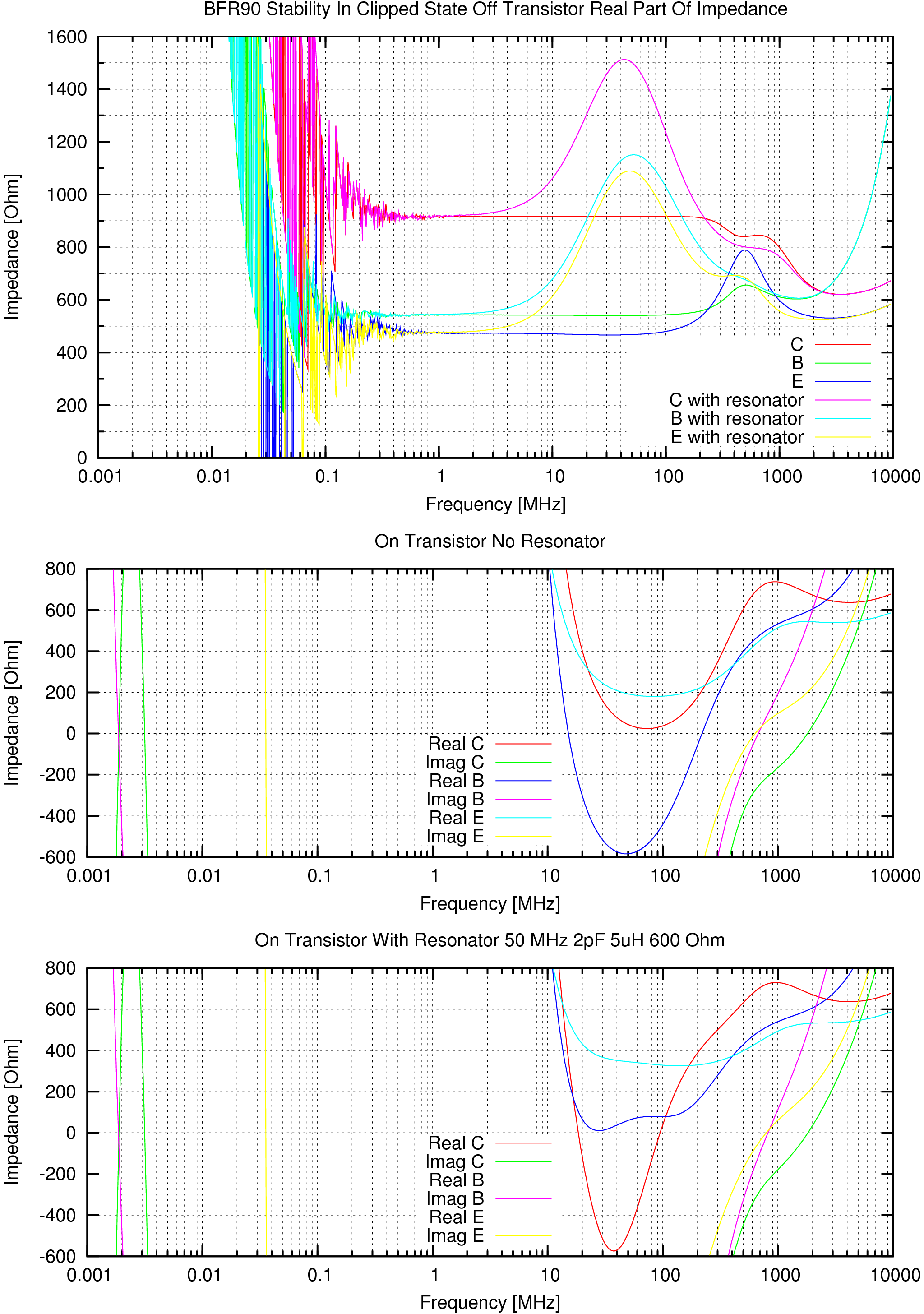
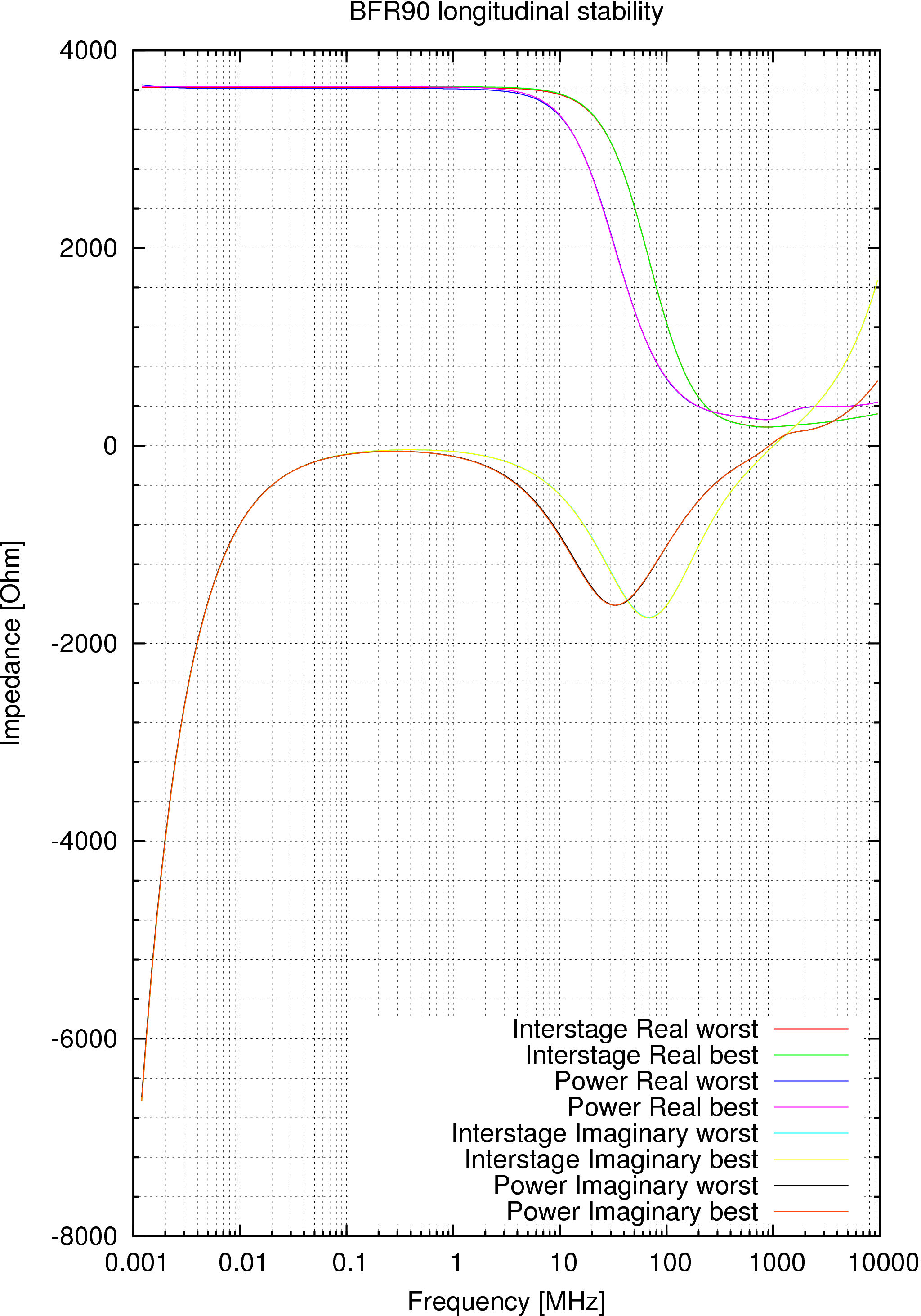
| I have taken just one cell without being loaded. The question is what has a tendency to be less stable the last cell of the chain or the ones before? I don't know. I had to remove the interstage capacitors because the DC current wouldn't otherwise propagate through them. They won't have a big effect on high frequencies where instability is a risk. | |||||||||||||||||||||||||||||||||||
|
|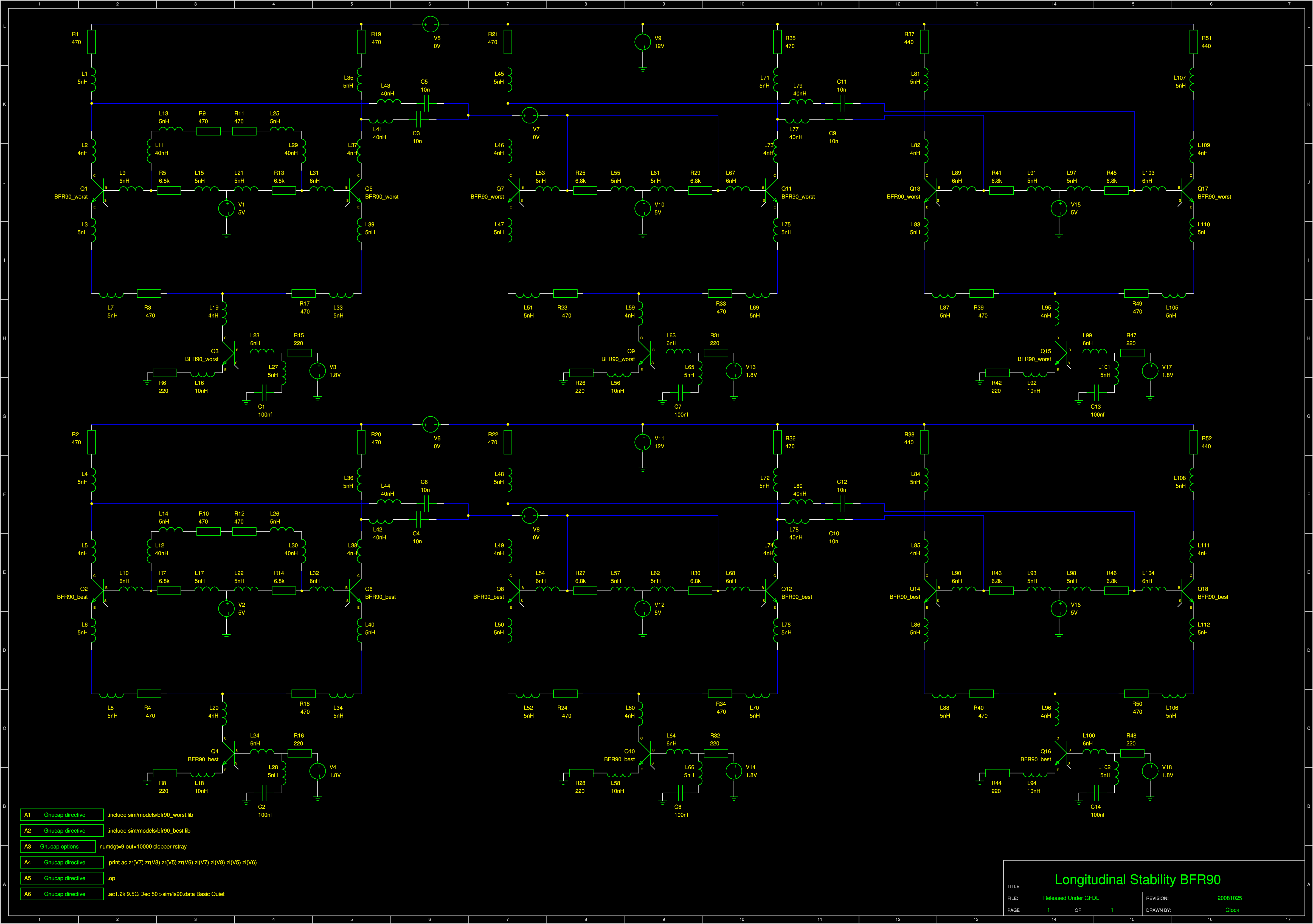
|
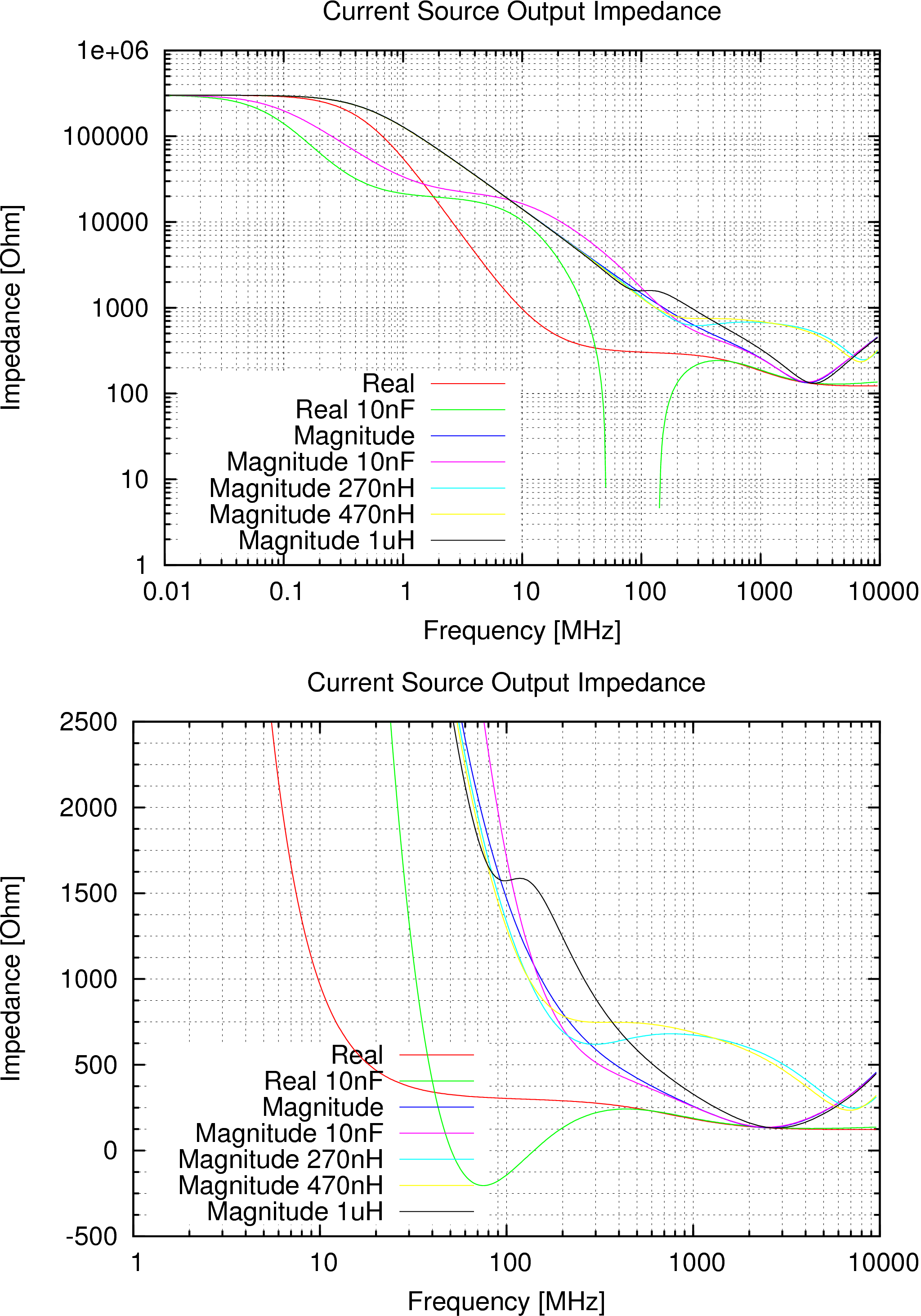
Current source output impedance. Once direct, once with a 10nF between base and emitter for "slower transistor which is not so prone to oscillation" (hahaha ;-) ). I took 10nF because higher value tend to be more expensive, took the Distrelec price list. | |||||||||||||||||||||||||||||||||||
|
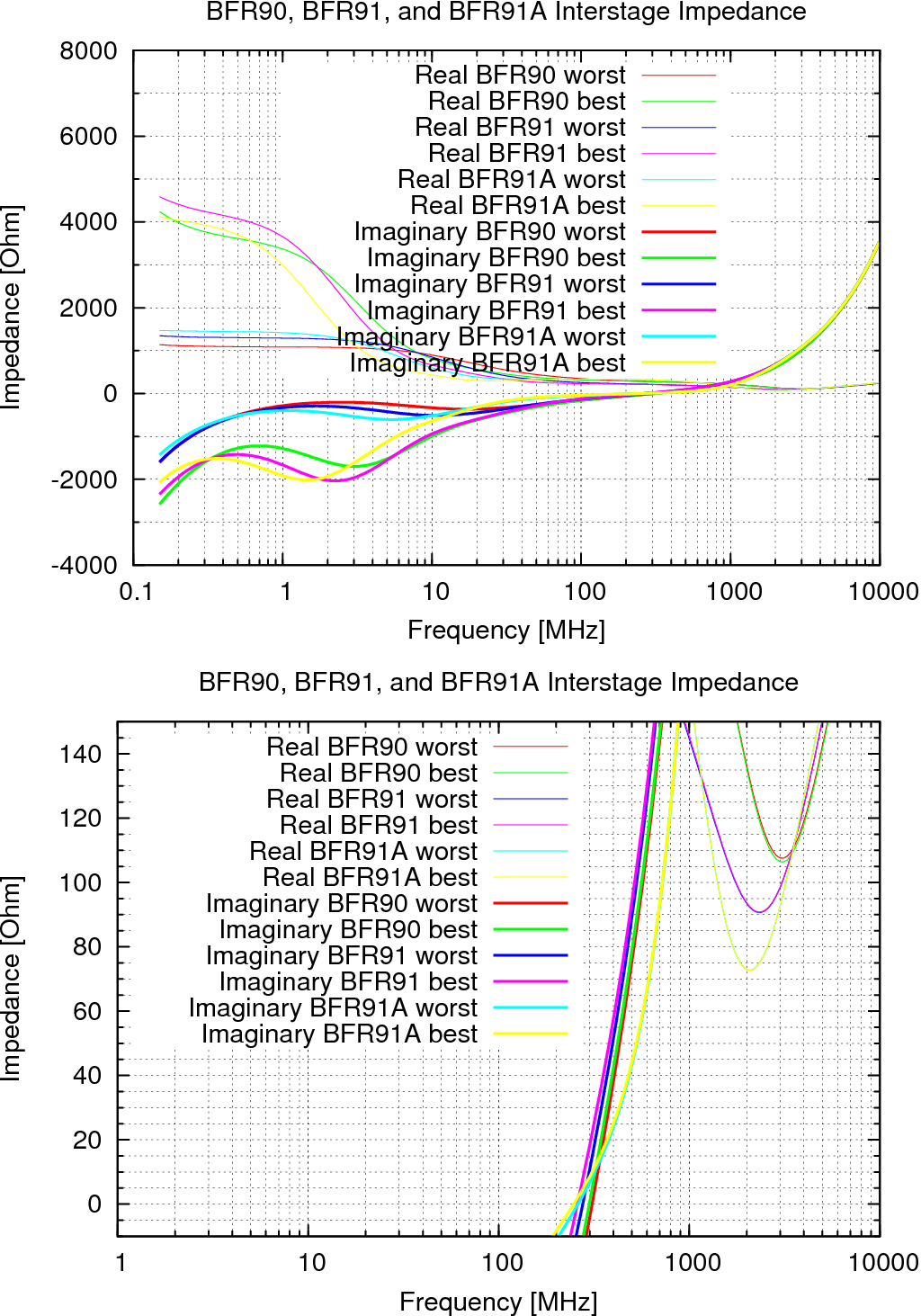
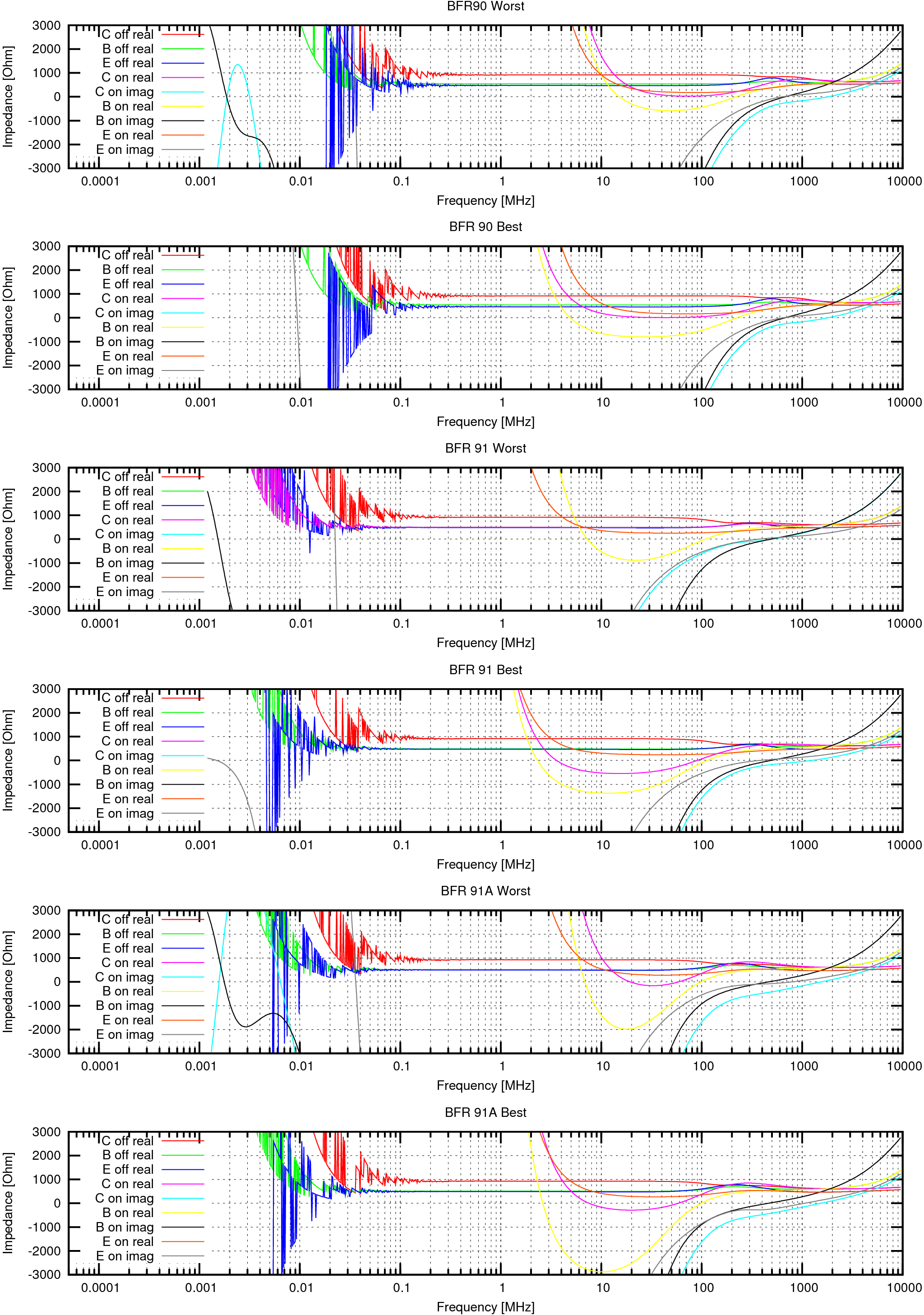
Without the capacitor it is stable (at least from collector point of view), just the current source has reactance of 15kOhm @10MHz which corresponds to 1pF. Good intentions with 10nF brought a catastrophic result. It has tendencies to oscillate! But even without the 1-nF there is a danger the cell will actually have a small amplification at high frequencies and longitudinal mode. There is a longitudinal noise coming from the switching (limiting) action of the cell which could propagate to the end stage. Or this noise could add to the wanted signal. Let's try to add a parallel LR filter in series with the collector to improve the characteristic at high frequencies. We would have to get such a high impedance on the coil to actally get above the 1pF line in the graph. Problem is the coils have an interwinding capacitance which spoils our effort. Let's look at CM322522 from Bourns, a coil that is not expensive (1,18 CHF at Distrelec October 2008), has apparently good HF properties is not big and I have already used in Twister2: See the Bourns Coil Datasheet and the Murata Datasheet :
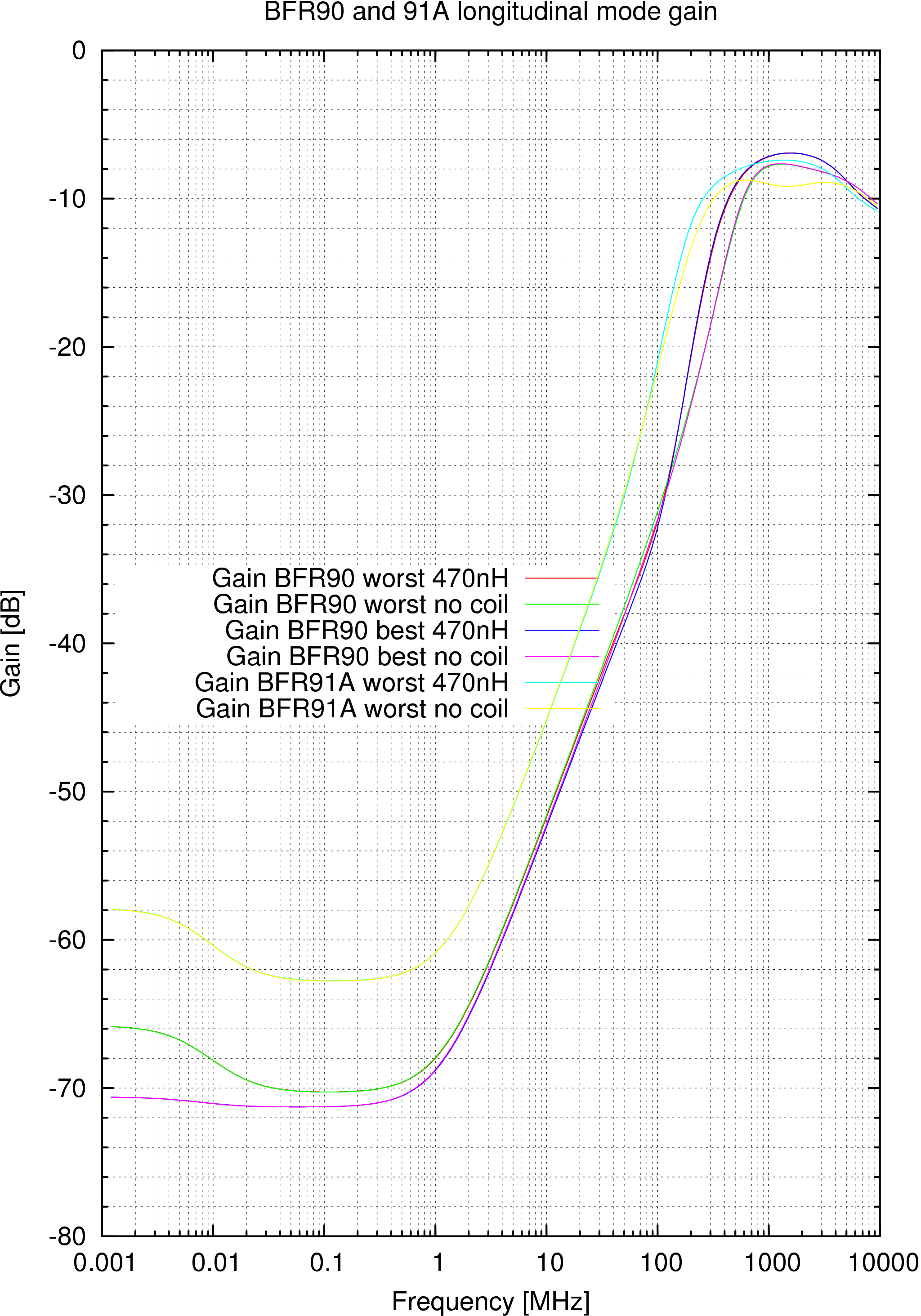
I have adjusted the resistors parallel to the coils for a roughly monotonic frequency response. I think the best choice is the 470nH Murata. It keeps the impedance magnitude above 470 Ohm until about 2.5GHz where the transistor has a negligible gain (2x at least) anyway. Now I put these current sources with LR chokes into the transient response simulation to get a more precise picture. |
|
| |||||||||||||||||||||||||||||||||||
|
|
|
| |||||||||||||||||||||||||||||||||||
|
No negative resistance. Stable. |
|
| |||||||||||||||||||||||||||||||||||
|
No negative resistance. Stable. |

 Contact, support: Clock
on the Internet Relay Chat.© 1998-2016 Karel ‘Clock’ Kulhavý et al..
Contact, support: Clock
on the Internet Relay Chat.© 1998-2016 Karel ‘Clock’ Kulhavý et al.. 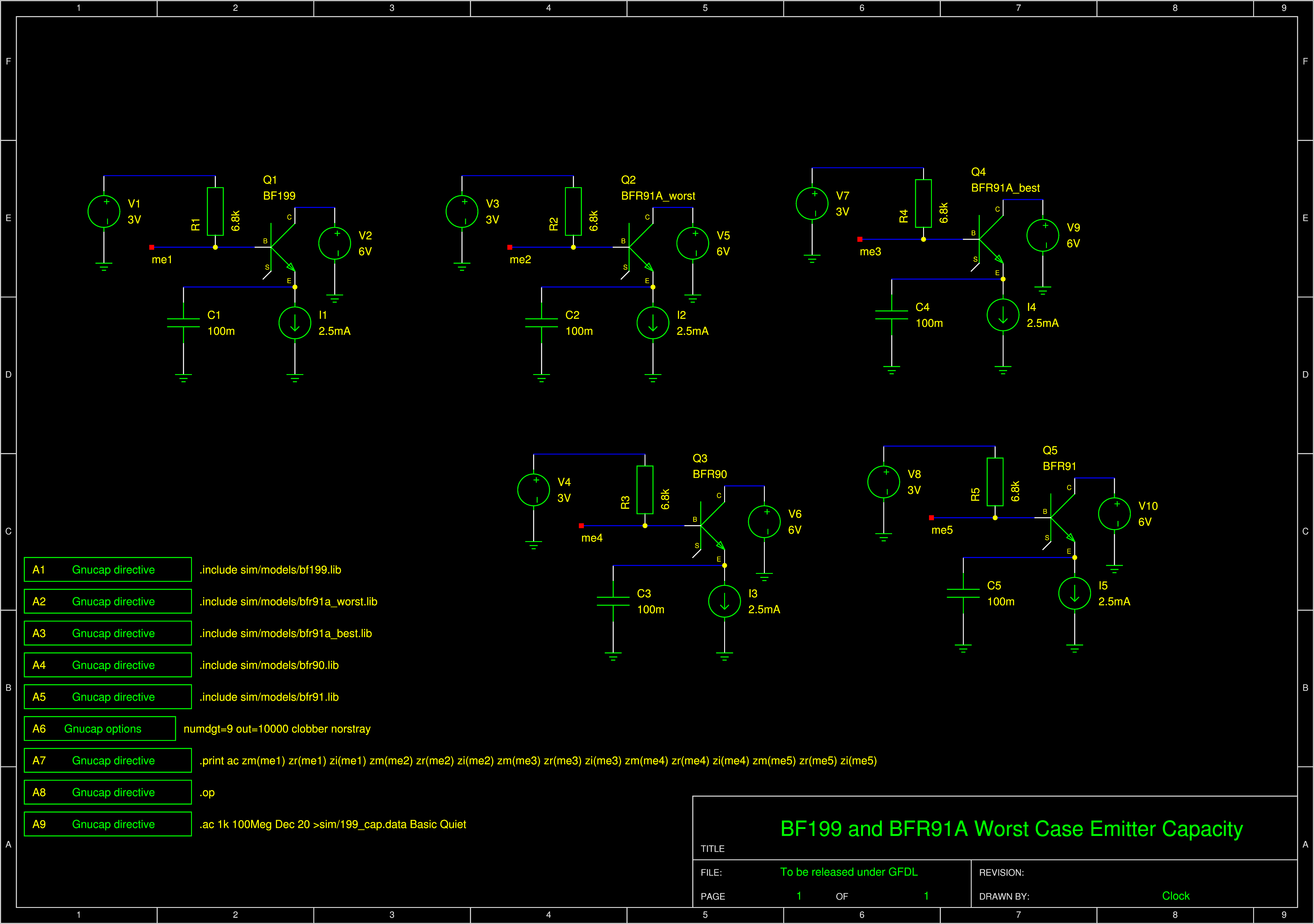


