![Gallery[1762]](http://images.twibright.com/tns/lvl2/1762.jpg)
Ask on the Mailing list and I'll add the question and answer here.
The purpose of Twister2 is to add and remove 1MHz signal to and from the gaps between individual Ethernet frames. On wired Ethernet, there is silence between frames. On optical Ethernet, there is a steady 1MHz square wave between frames.
The transmission side of Twister2 first receives the data from wired Ethernet (T53, T54) using a differential receiver (U62) which converts them into logical levels. U54 is just a buffer. C66 and R52 replace leading edges in the signal with short H impulses and everrything else with L. U52 inverts the signal. The Schmitt trigger function of U52 is unused.
Then a cascade of three pulse extenders is employed (U63-65) to figure out when packet is received and when not. This cascade also removes the link integrity pulse from the signal. On every leading edge of the original signal, U63 gets reset to zeroes on all outputs. On every tick of the 16MHz clock (62.5ns) one tap gets set to one. That means if the output is on the 5th tap, it gets set from 0 back to 1 after 4-5 ticks after the short resetting pulse ends, that means after 250-312.5 ns minus the duration of the short impulse it gets back to H.
If the incoming signal has the leading edge pitch less than 250ns minues length of the short impulse, then the output stays permanently in 0. If it has more, then it will contain ones interspersed with zeroes.
The Manchester signal has maximu leading edge pitch of 200ns. The silence between the packets takes at least 9600ns. So packets will produce zero on U63-10 and the interframe gaps one.
Link integrity pulses would trigger a false packet alarm. Therefore U64 and U65 are there to clean this out.
The idea behind is that if a fast signal is pulse extended then the individual pulses blur together and create a steady level. If a slow one is pulse extended they don't blur and stay as a frequency.
Crystal oscillator (U69) makes 16MHz which is divided by 16 by a binary counter (U59). This signal is then multiplexed by U54, U56 which is at the same moment the coax driver. The gating is controlled by the signal which says if packet is being transmitted or not. The driver drives the coaxial cable where the signal travels to the roof. TX indicator D54 shines when packet is transmitted, i. e. with long bursts of traffic it invisibly flickers with every interframe gap.
The reception side of Twister2 first receives the data from coaxial (U62) and cascade of two pulse extenders (U51, U53) determines when a packet is being received and when not.
The 16MHz master clock is divided by 2^18 (262,144) by ripple carry counters (U60, U61) and a link integrity pulse that lasts 125 nanoseconds (2 cycles of the master clock) and repeats every 16.384ms is decoded from the binary count. The decoder polarity is selected in a way that the propagation of the ripple carry through the counter stages can't cause improper decoding.
The link integrity counters are held reset during reception of a packet. During all zeroes, the link integrity impulse is not decoded. When a packet ends, the counters run and only after approx. 16.384ms the first impulse comes. This prevents an incomplete impulse or glitch being generated should the impulse accidentally hit a packet boundary.
The link integrity signal is multiplexed instead of the 1MHz from the optical input between frames by the multiplexer U55, U54, again the packet presence signal is used as control signal for the multiplexer. The LED is again driven by the packet presence signal.
Twisted pair driver U58 is connected in tandem to be able to generate three-state output - positive voltage, negative voltage (used for packet or link integrity pulse) and zero (used for interframe gap).
Switches S1 and S2 are used to swap RX and TX pairs on RJ45 to select between PC or switch. They can also be configured to connect the RJ45 connector into a loopback.
The remaining fourth position is a side effect of the design and causes the transmitted data from Twister and PC or Switch to clash and being received at the same by the PC or Switch. This shouldn't be able to cause device damage because the voltage levels are quite limited and the drivers have a defined output impedance so they don't drive into a short circuit.
An integrated controller (U68) controls a switched mode power supply (L51, D53, C70-71) where special care was taken to filter out the switching noise from the power lines going out of the enclosure (L52-54, C80-81, C72, 76-79, 84, 85). At the same time, L53-54, C72,76-77,79-81, 84-85 create a filter that prevents noise from external power supply line to enter the coaxial cable shield connected to CONN52 or CONN53.
The internal power supply is not filtered using a coil because the logical gates are tolerant to certain switching noise and the line receivers are designed for high power supply and common mode rejection.
D55 acts as a crowbar protection if the external power supply is applied with reverse polarity.
The signal is for maintaining defined DC level of the signal and to key out receiver noise and unwanted signal from being amplified in the limiter. Ronja 10M Metropolis would not work without the 1MHz signal. Packets would be randomly lost due to received packet echoes from the opposite direction on shorter links, sometimes even on longer links due to random noise resembling a preamble, and most importantly, the remaining would not be received at all because corrupted preamble would be received by the AUI interface.
Fiber-optics trasceivers use also this 1MHz signal for stuffing space between packets so that Ronja is compatible with them.
It has been determined by changing geometry of this wires and seeing how strength of the garbage changes. If 100nF capacitors are placed where the wires leave the box, this is diminished to 2mVpp.
Currently there is the coaxial power jack, but it should be removed in the future because:
I have a belief that only gold-to-gold contact or contact with strong mechanical structure and plastic deformation can provide reliable contact. This belief is supported by experimental evidence and by theoretical reasoning regarding oxide layer forming on the boundary.
This magic circuit is made of pulse extenders. Pulse extender is a device that extends the duration of one level (for example H) for some given time. If the pulses are so close that the extension would overlap the next pulse, then the pulses merge together.
A pulse extender has some minimum duration of pulse. If the pulse is shorter then it doesn't notice there was any. In this case it's the minimum hold time for RESET of the shift register which is very short (couple of nanoseconds) and therefore doesn't pose any practical limitation.
Each of the U63, U64, U65 is a shift register. Each works as one pulse extender. There is some random imprecision in how much the extender extends, that's given by the fact that the Twister clock is freewheeling compared to the signal clock. But it doesn't matter for reliable operation, this effect was accounted for in the design.
The purpose of the circuit is to determine if the PC/switch is transmitting a frame at the moment or not. First the edges are separated from the signal into turning them into short impulses (and discarding the other edges) with the gate with capacitor and resistor before U63. That makes the circuit insensitive to the level in which the line receiver happens to be stuck in when idling between frames (there is a half-level in between the frames which is neither 0 nor 1)
Then the little 10MHz or 5MHz pulses in the frame are merged together by U63. That gives us a raw signal. The duration of this signal is then adjusted at the beginning and at the end with U64 and U65 to get the right timing so it works reliably with the IEEE802.3 specified timing in all thinkable situations. The timing is also selected in a way that Link Integrity Pulses are discarded. They are not packets and we cannot transmit them, because there is no way how to encode them reliably when they are wrapped around by a 1MHz signal.
When calculating the constants, it was difficult to numerically tune it in a way that all the mutually opposing requirements of the timing are met. But I believe it works reliably and shouldn't be tampered with.
The pulse extenders in AUI Forte were done with capacitors, resistors, diodes and Schmitt trigger gates. But because of component tolerances, the timing was so relaxed, that it was good for AUI but is not good for TP anymore. So I had to redesign it with digital pulse extenders - shift registers. These have jitter as opposed to analog ones, but the jitter can be made arbitrarily small by selecting the clock frequency and doesn't depend on temperature or component tolerances.
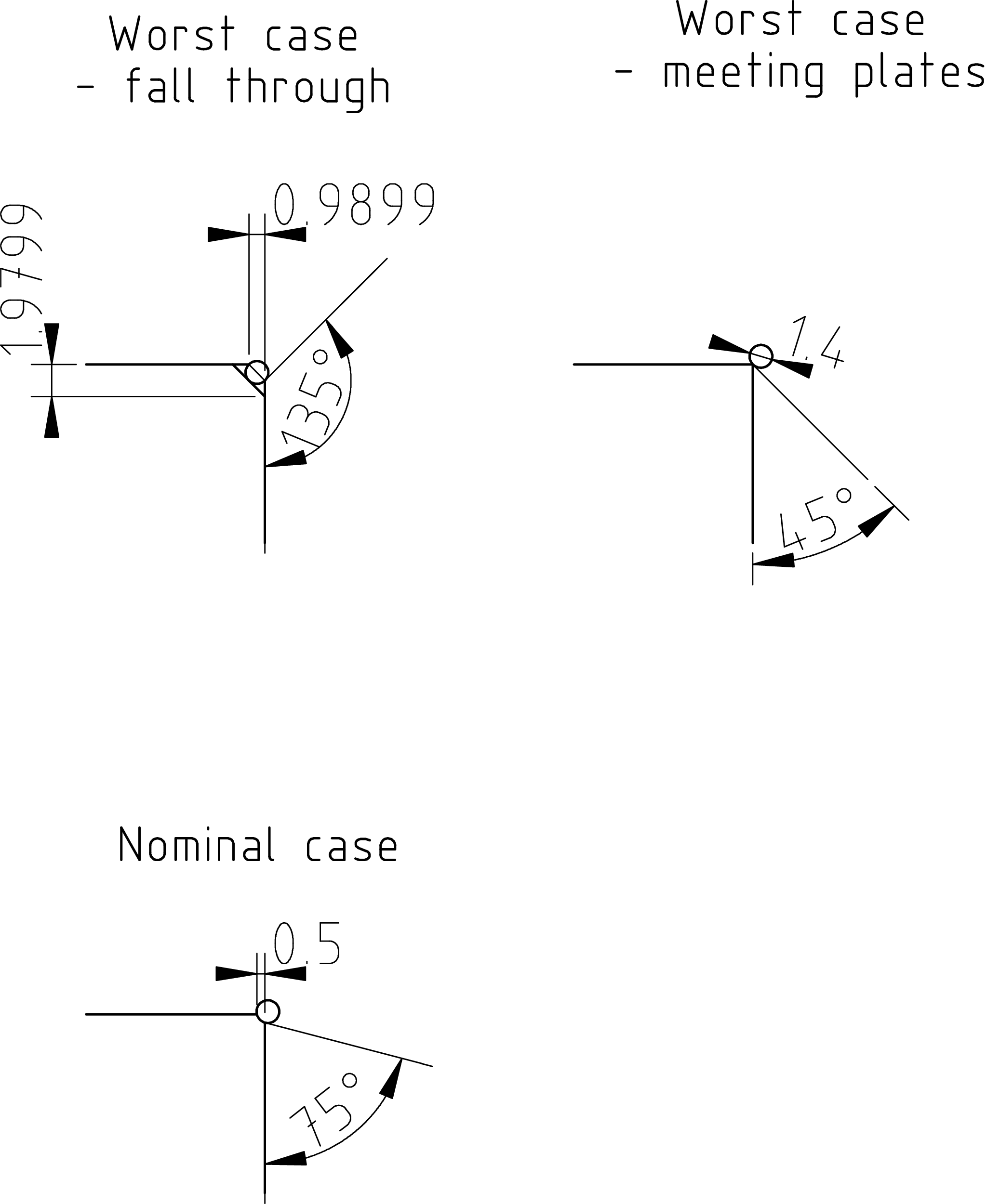
The corners in Twister2 are designed with a 1.5mm^2 copper wire inlay. Making straight corners from touching tins has the following disadvantages:
The copper wire can sit shallower or deeper in the slot, therefore compensating the manufacturing imprecisions. Furthermore they provide round edge and when bent and then soldered down, even a round corner.

 Contact, support: Clock
on the Internet Relay Chat.© 1998-2016 Karel ‘Clock’ Kulhavý et al..
Contact, support: Clock
on the Internet Relay Chat.© 1998-2016 Karel ‘Clock’ Kulhavý et al.. 