 |
Overview We are going to build a box with PCB soldered
permanently inside by it's rims. The box is made of metal and is closed with a
lid from both sides. The mounting barrels in the pictures are obsolete, now
there are mounting brackets. |
|
|
|
|
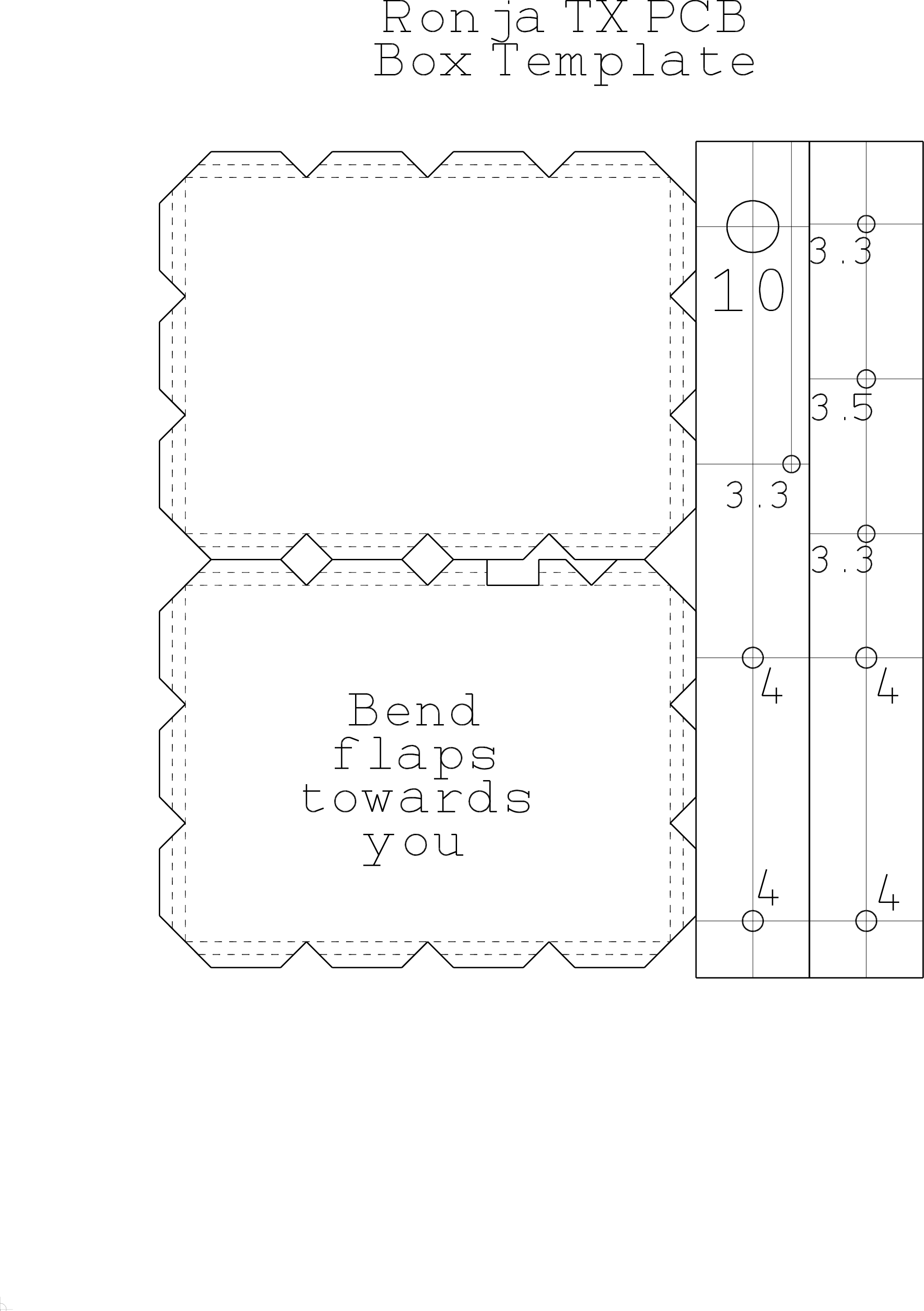
Handmade box
If you don't have factory-made box, make two lids and two
drilled strips of tin according to this
template. |
|
|
|
|
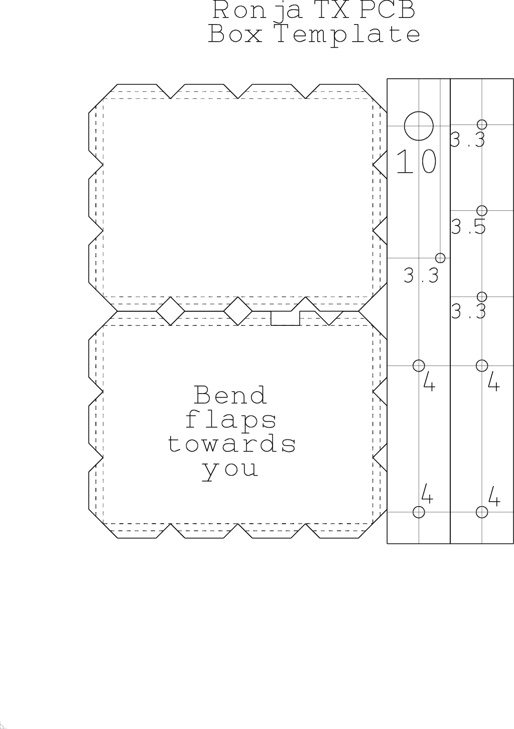
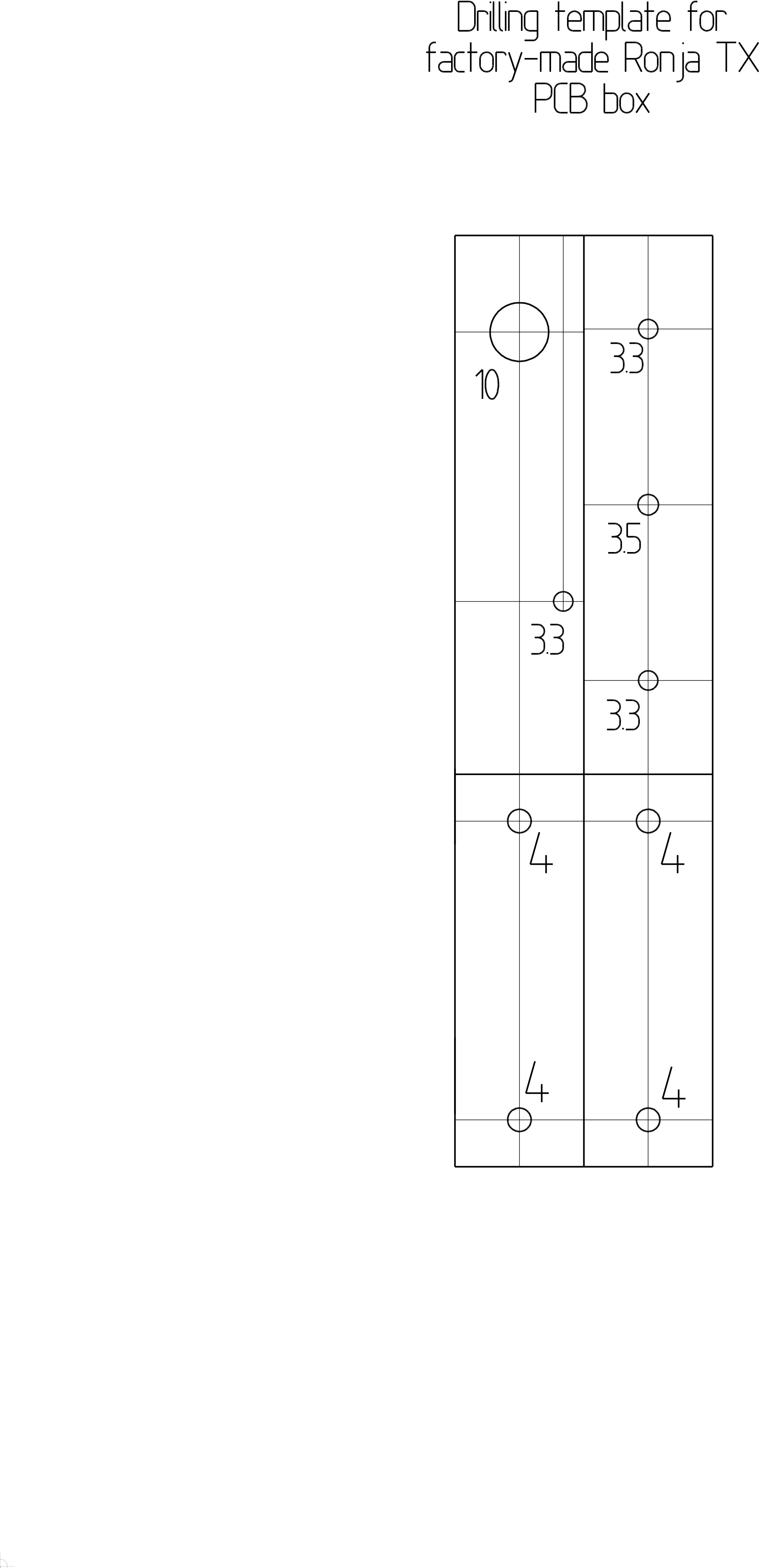
Factory box template
If you have a factory made box print out this drilling template. |
|
|
|
|
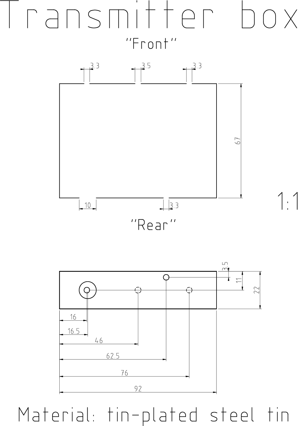
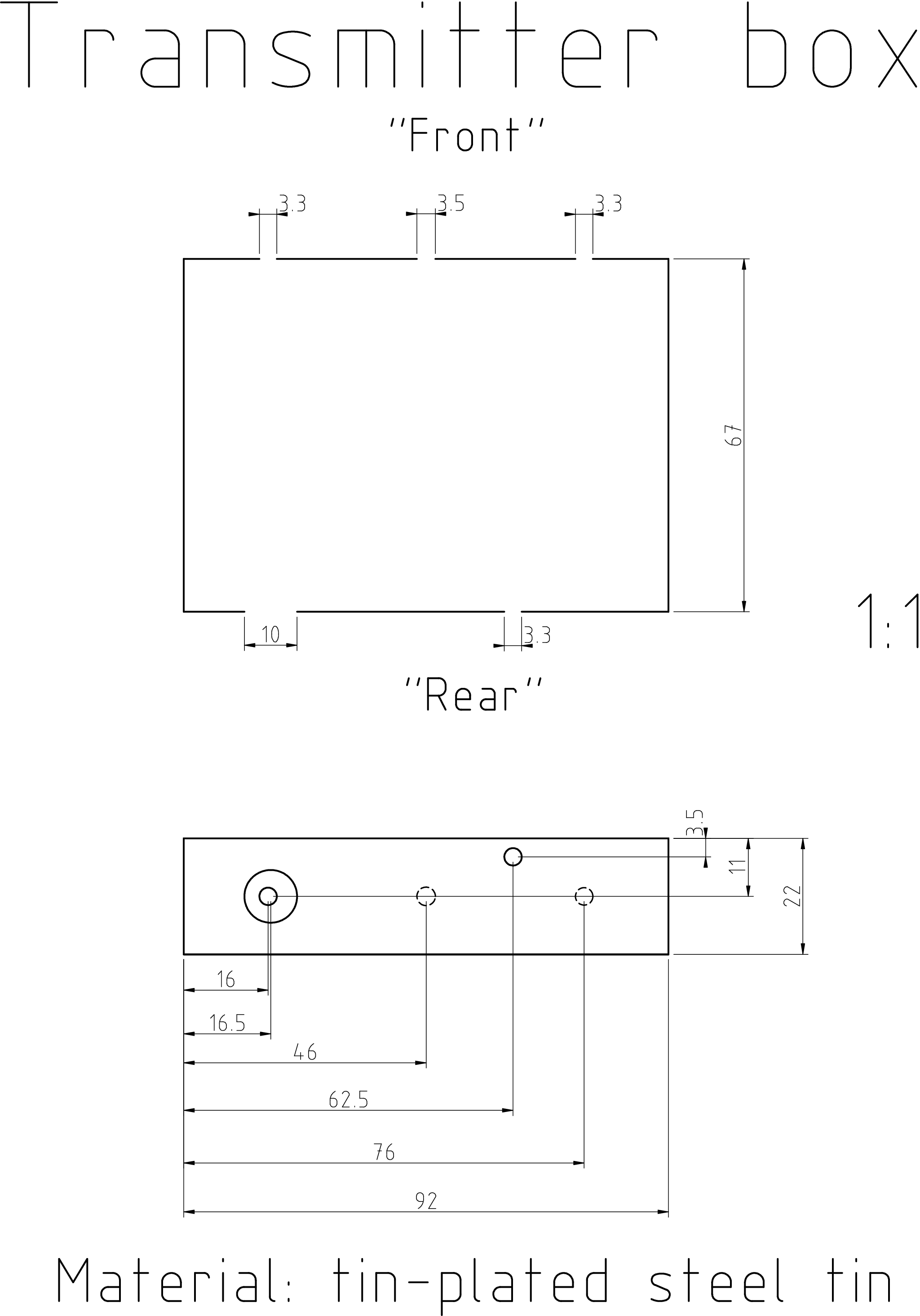
Factory box drilling If you have a
factory box, drill it out, according to the drawing and the factory box
drilling template which you glue on. Note: no barrels should be present
in any of the pictures in this box. One template in the pictures is missing
the 3.3mm holes. |
|
|
|
-e
|
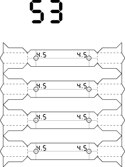
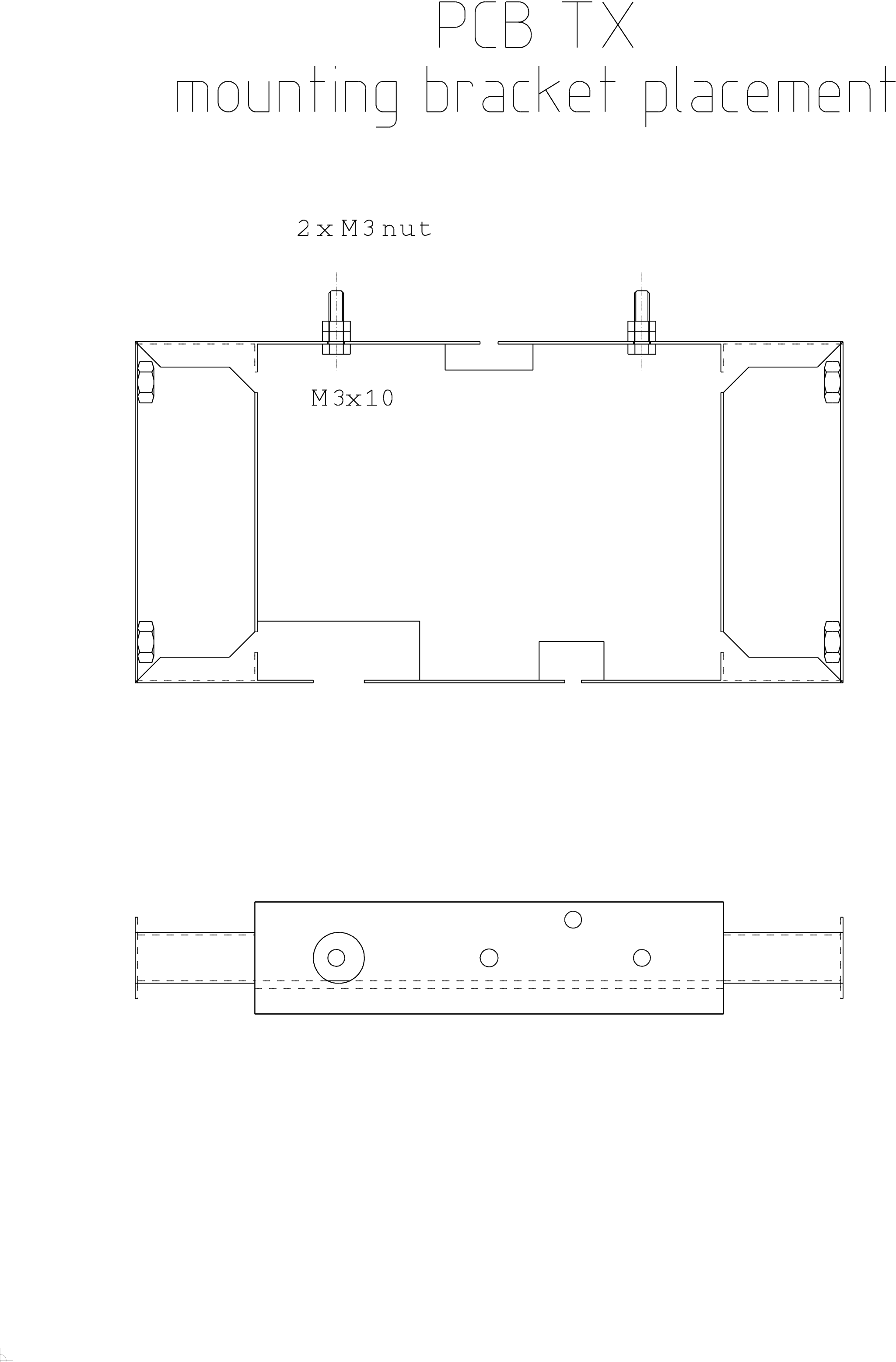
Bracket Template If you plan to
build optical head and the pipe has diameter less than 105mm, skip this box and
the next one. Subtract box width (normally 92mm) from the optical head's pipe
inner diameter. If you don't plan to build optical head, assume 145mm.
Select the template according to the resulting number from the Side template list and print it. The template
is for two boxes, you need just half of it. |
|
|
Make the brackets
- Drill the side template out and bend it. Wash the template off in warm
water.
- Solder the M4 nuts over the holes from the inside.
|
|
|
|
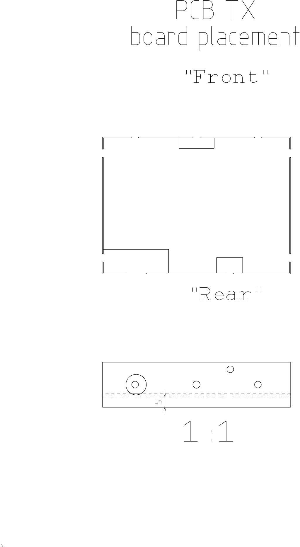
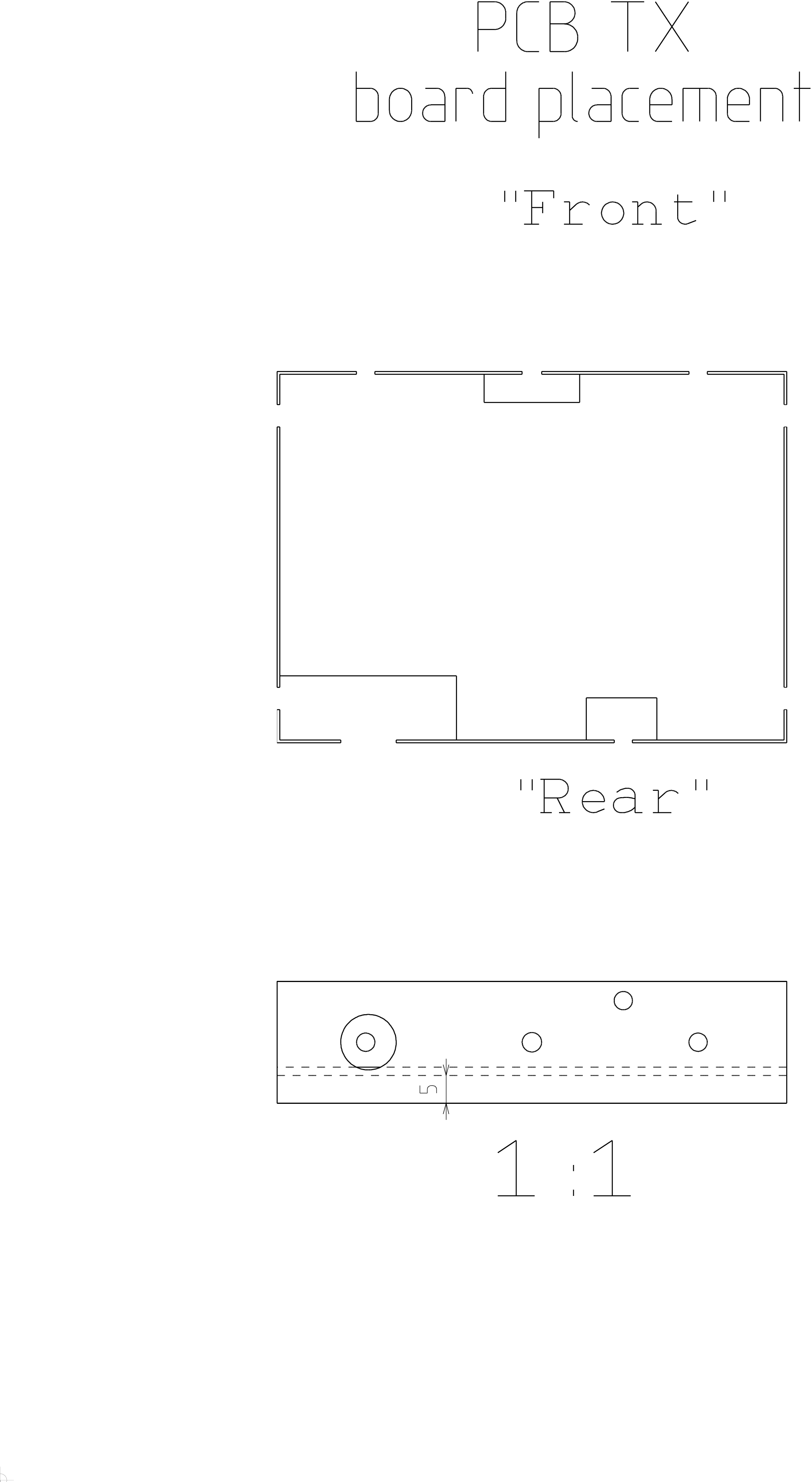
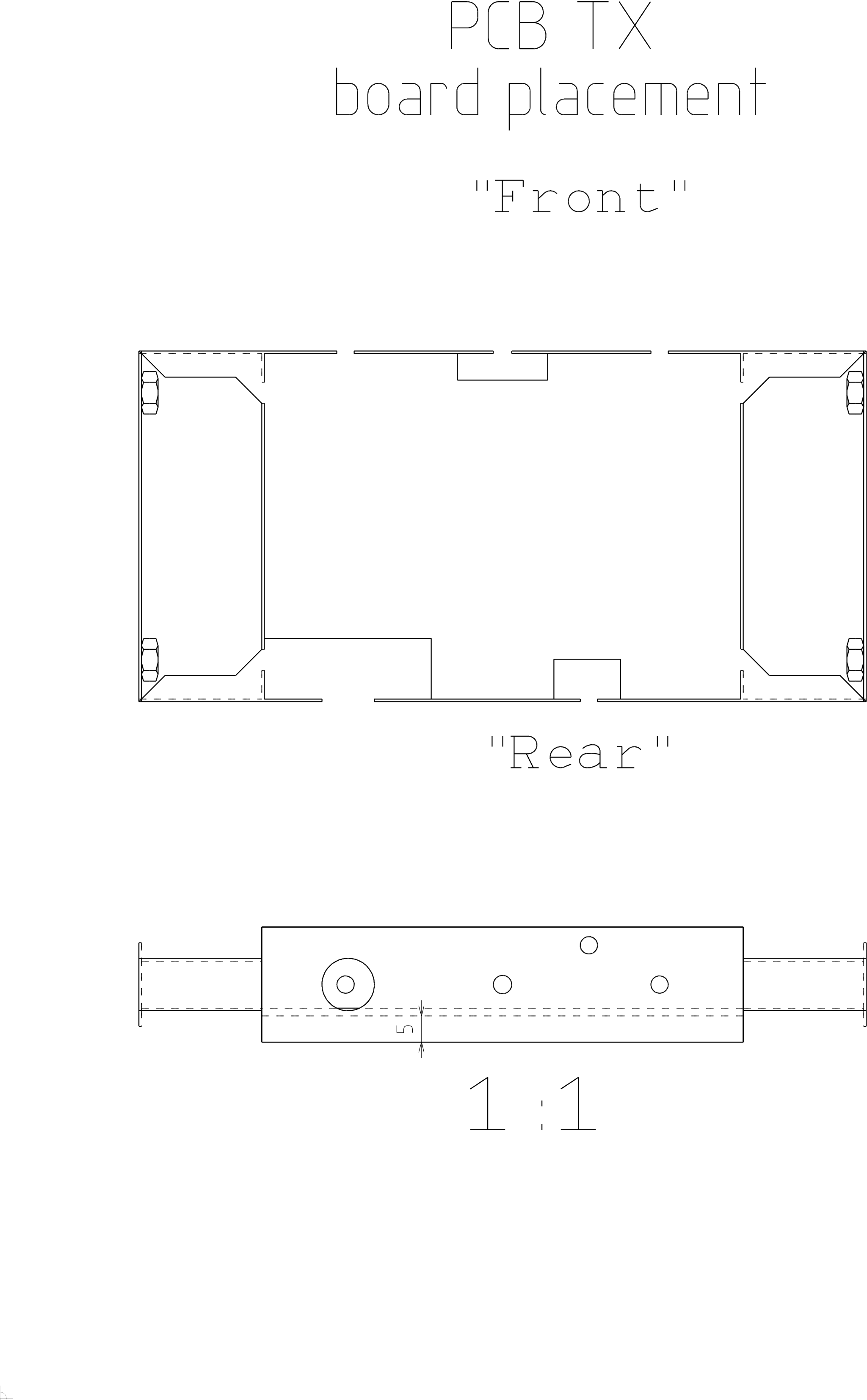
Soldering board into case
- Watch the drawing how is the case and board assembled and oriented
- Remember solder side of the board will be 5mm deep in the box
- If you have handmade box, shape the two strips of metal around the PCB,
solder and cut the excess. Otherwise trim the PCB size by file until it
fits into the box.
- Solder the board to the box continuously along the edges
|
|
|
|
|
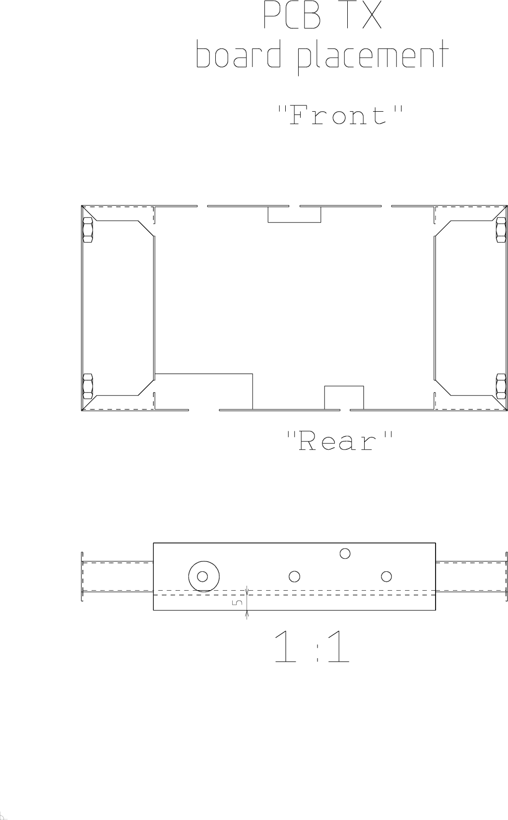
Solder on brackets/nuts
If you have brackets, then solder the brackets to the case, otherwise solder bare
M4 nuts from the outer side over the 4mm holes. |
|
|
![Gallery[1b4f]](http://images.twibright.com/tns/lvl2/1b4f.jpg)
|
Contact flaps
- Please note that the barrels in the picture are obsolete, there
should be mounting brackets.
- Make contact flaps
on both lids of the case using tin cutters.
- Adjust their angle by pliers so
that every flap is sprung against the case when the lid is closed.
- If not already done, cut away the flaps around the small hole for regulator (as seen in
the big picture).
|
|
|
|
|
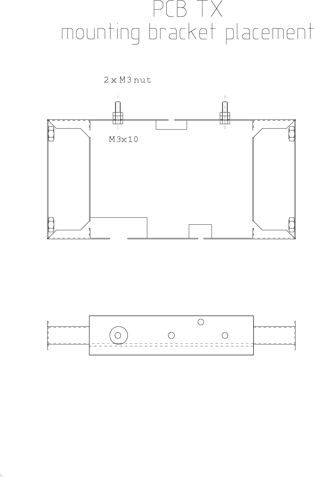
M3 bolts
Install 2 M3 bolts and 4 M3 nuts as in the picture. Tighten. |
|
|
![Gallery[13fc]](http://images.twibright.com/tns/lvl2/13fc.jpg)
|
Making the coil
Take the 8.5mm bit and wind a 10-turn coil on it from the insulated
1mm^2 hard copper wire.
![Gallery[13fd]](http://images.twibright.com/tns/lvl1/13fd.jpg) |
|
|
Part lists
Print one part list from these according to your storage method. It will be used during population of the
PCB:
|
|
Warning: fopen(../schematics/metropolis_transmitter/metropolis_transmitter.pcb.output_assembly.php): failed to open stream: No such file or directory in /home/clock/www/twibright.com/ronja/boxed_page.php on line 103
Warning: filesize(): stat failed for ../schematics/metropolis_transmitter/metropolis_transmitter.pcb.output_assembly.php in /home/clock/www/twibright.com/ronja/boxed_page.php on line 104
Warning: fread() expects parameter 1 to be resource, boolean given in /home/clock/www/twibright.com/ronja/boxed_page.php on line 104
Warning: fclose() expects parameter 1 to be resource, boolean given in /home/clock/www/twibright.com/ronja/boxed_page.php on line 105
|
|
Populating
Print out this assembly plan. Populate the board in this order:
- Resistors except R12-R16 (those are not on the board)
- Diode (not LED)
- All IC's except U4
- Electrolytic capacitors
- Capacitors
- Transistors
- Coil
|
|
|
![Gallery[1b5b]](http://images.twibright.com/tns/lvl2/1b5b.jpg)
|
Installing regulator
Material:
- 1pc. bolt M3x6, galvanized, hex or Allen or Philips or cheese head
- 1pc.. nut M3, galvanized
- 1pc. toothed spring washer M3 (3.2mm), galvanized
Install the 7805 regulator according to the photos. Place thermal paste between
the regulator and case for good thermal contact. |
|
|
|
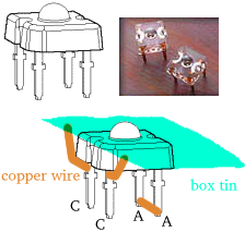
Transmitter LEDPut the HPWT-BD00-F4000 LED
into the 3mm hole in front of transmitter case and solder cathode (C) directly
to the round pad on the PCB. Solder anode (A) with short pieces of 1mm^2 wire
to the square pad. Solder cathode (C) with another pair of wires to the metal
box. These wires, besides grounding, will conduct heat and cool the
LED. |
|
|
Correctness check
- Check that all IOs, diodes, transistors and polarized capacitors are
oriented the right way.
- Check that all IOs and transistors are the right type.
- Check that no component is missing
- Correct values of components
- That cables are soldered on the right pad
|
|
 |
WarningWhat do you think would happen if you skip this correctness
check? "Your board would come to a screeching halt and you'd fly.
And you'd smash cement." -- Stacy Peralta, Dogtown and Z-Boys" |
|
|
|
|
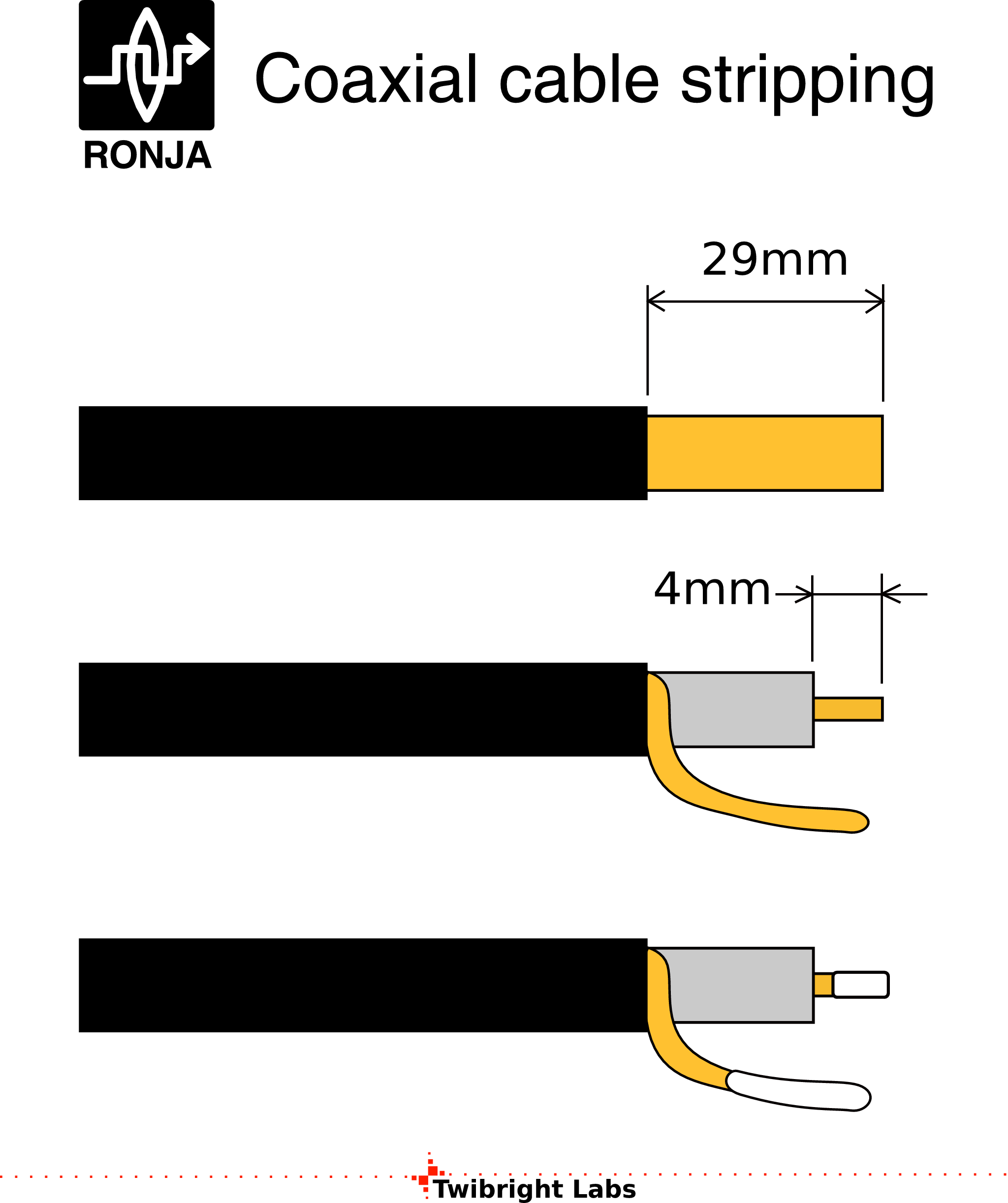
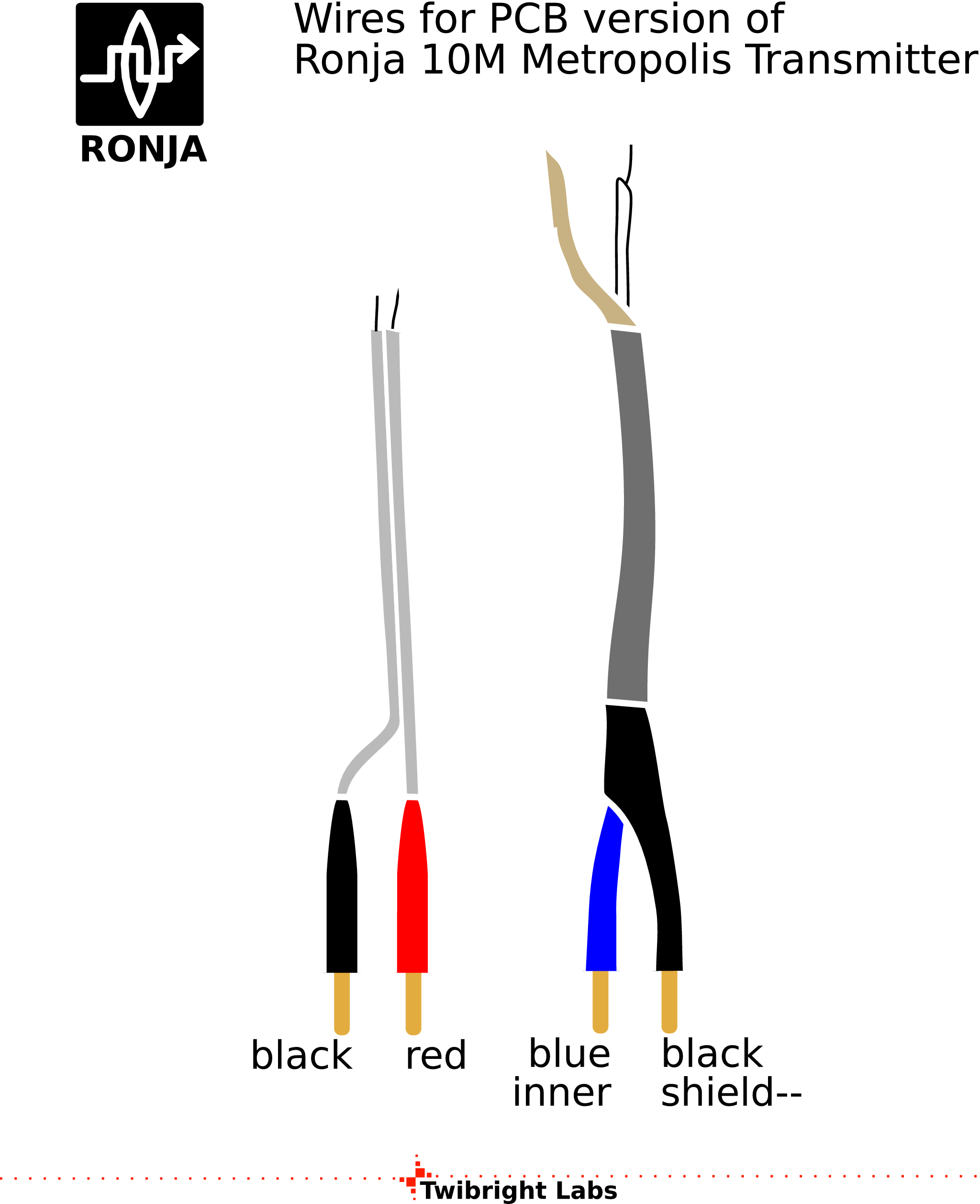
Stripping
- Take 20cm stranded
double-conductor cord 1.5mm^2 and 20cm shielded stranded single-conductor with
solderable shield.
- Strip 4mm of insulation from the unshielded cable on one sides.
- Strip 29mm
of the outer insulation from the shielded cable on one side. Strip 4mm of the
inner insulation from the shielded cable on one sides.
- Cover all bare ends with solder.
|
|
|
|
|
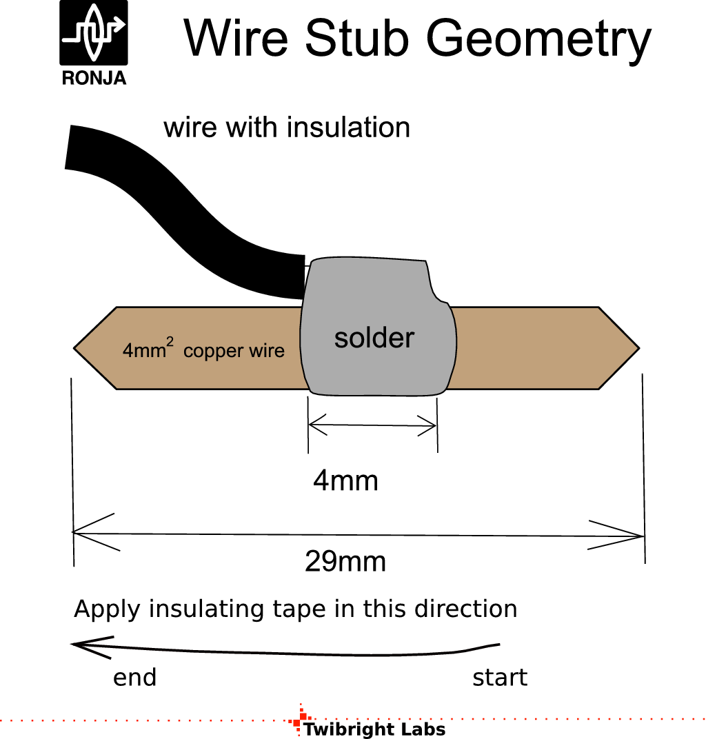
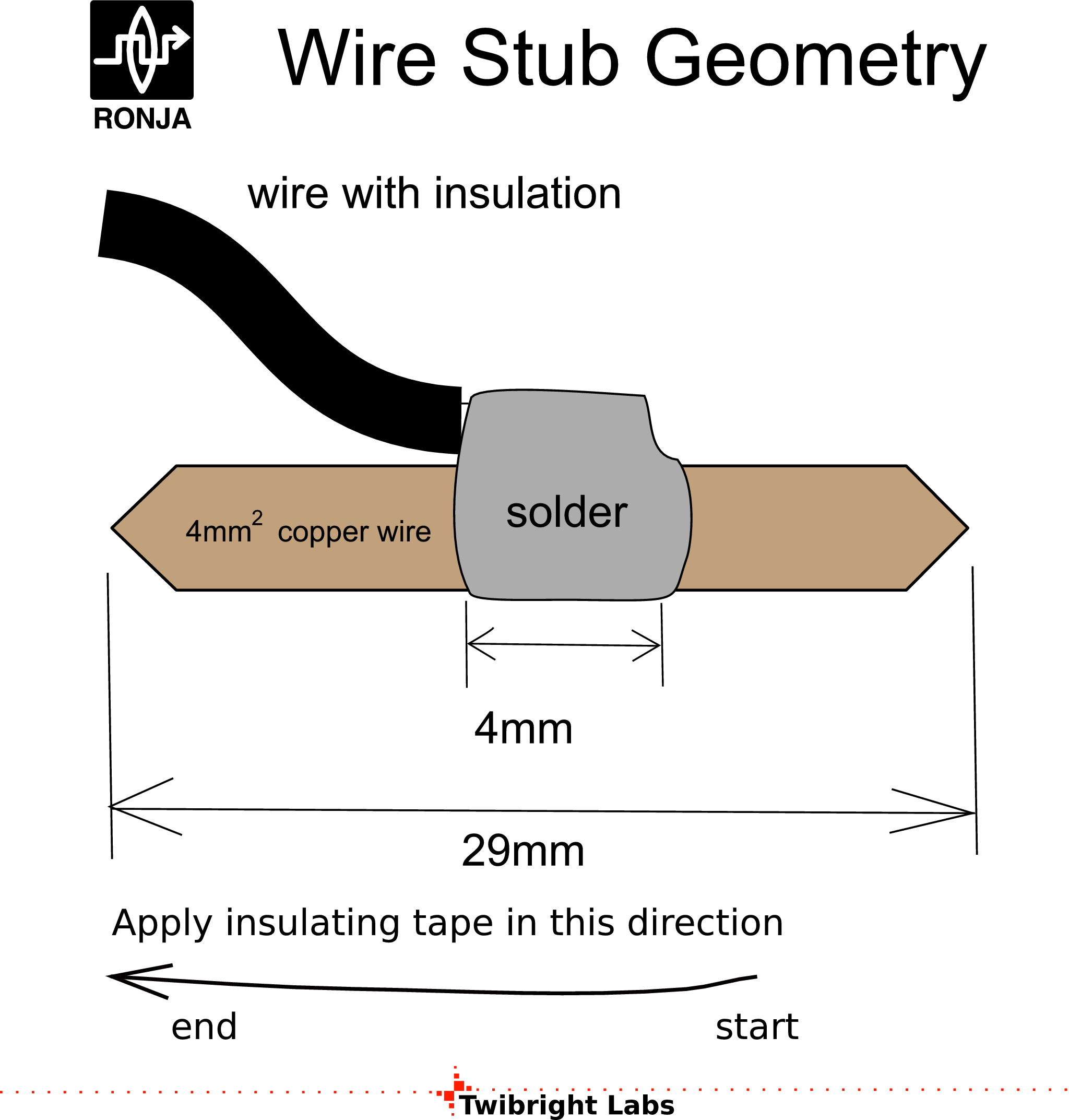
Copper stubs
Solder 4 copper stubs made from 4mm^2 uninsulated hard
copper wire on stripped ends of both conductors.
|
|
|
|
|
Colour insulation
- Insulate the stubs with colour duct tapes according to the diagram.
- Strip remaining ends of the unshielded cable in 4mm length
- Strip shielding from remaining end of coaxial cable in 10mm length
and the inner wire in 3mm length
![Gallery[1b6a]](http://images.twibright.com/tns/lvl1/1b6a.jpg) |
|
|
|
|
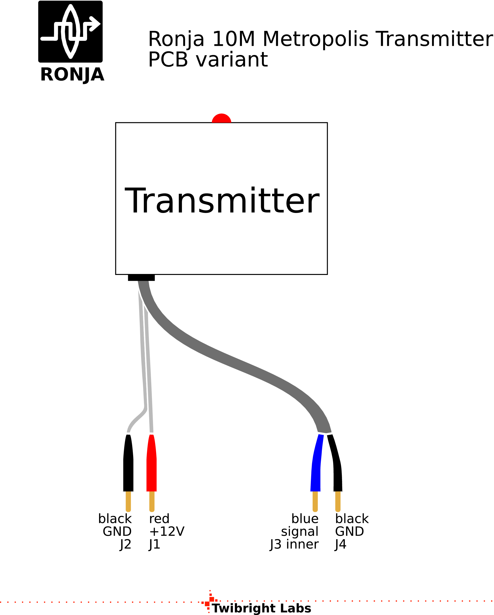
Installing wires
Install the wires, solder them inside to square soldering pads and fix
them in the hole from both sides by fair amount of thermal glue or silicon
putty. |
|
|
![Gallery[1b7d]](http://images.twibright.com/tns/lvl2/1b7d.jpg)
|
Washing and inspection
Wash the device in isopropyl alcohol. Store the dirty isopropyl alcohol for
re-use as pre-wash for other boards. Inspect all soldered places that they
do not contain cracks or shorts and their surface is not wrinkled. Repair
those that are bad by re-melting with rosin flux. |
|
|
Small schematic
Print out the schematic on a piece of paper size 90x60mm. Overwrite all part
numbers that have been installed different than in schematic. Overwrite all
resistor values that have been chaged during tuning. Write down amplification
factors of both 2N3904 transistors. Glue the paper on the inner side of the
lid. |
|
|
|
Labelling
Print out the Ronja 10M Metropolis Transmitter label.
Fill in and glue on the
outer side of one lid.
|
|
|
![Gallery[1b81]](http://images.twibright.com/tns/lvl2/1b81.jpg)
|
Closing
Close the lid without label on the side near circuit board. Try to close on the
other lid. If the regulator bolt head is in the way, cut out a notch in the lid
flaps using tin shears, then close. |
|
|
M4 bolts
Screw the M4x8 bolts into barrels. Your transmitter is now ready. |
|
|
|
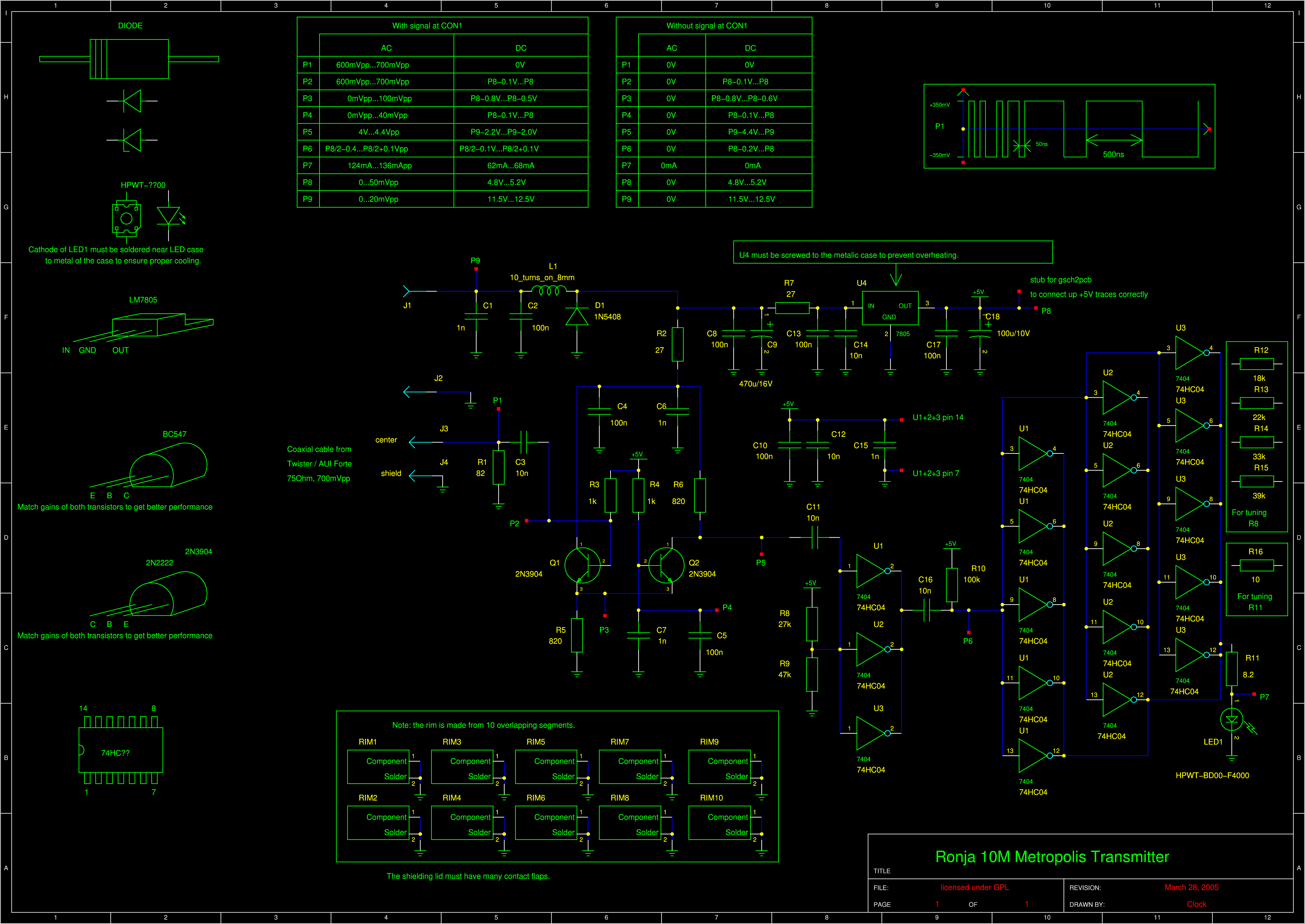
Schematics
Not needed for building - just for completeness. |
|
|

 Contact, support: Clock
on the Internet Relay Chat.© 1998-2016 Karel ‘Clock’ Kulhavý et al..
Contact, support: Clock
on the Internet Relay Chat.© 1998-2016 Karel ‘Clock’ Kulhavý et al.. ![Gallery[1b3f]](http://images.twibright.com/tns/lvl0/1b3f.jpg)
![Gallery[1b50]](http://images.twibright.com/tns/lvl0/1b50.jpg)
![Gallery[1b5e]](http://images.twibright.com/tns/lvl0/1b5e.jpg)
![Gallery[1b53]](http://images.twibright.com/tns/lvl0/1b53.jpg)
![Gallery[1b76]](http://images.twibright.com/tns/lvl0/1b76.jpg)
![Gallery[1b84]](http://images.twibright.com/tns/lvl0/1b84.jpg)
![Gallery[1b80]](http://images.twibright.com/tns/lvl0/1b80.jpg)

![Gallery[1b38]](http://images.twibright.com/tns/lvl1/1b38.jpg)
![Gallery[1b39]](http://images.twibright.com/tns/lvl1/1b39.jpg)
![Gallery[1b50]](http://images.twibright.com/tns/lvl1/1b50.jpg)
![Gallery[1b4f]](http://images.twibright.com/tns/lvl1/1b4f.jpg)
![Gallery[1b51]](http://images.twibright.com/tns/lvl1/1b51.jpg)
![Gallery[1b5e]](http://images.twibright.com/tns/lvl1/1b5e.jpg)
![Gallery[1b5f]](http://images.twibright.com/tns/lvl1/1b5f.jpg)
![Gallery[1b44]](http://images.twibright.com/tns/lvl0/1b44.jpg)
![Gallery[1b40]](http://images.twibright.com/tns/lvl0/1b40.jpg)
![Gallery[1b4b]](http://images.twibright.com/tns/lvl0/1b4b.jpg)
![Gallery[1b4c]](http://images.twibright.com/tns/lvl0/1b4c.jpg)
![Gallery[1b4d]](http://images.twibright.com/tns/lvl0/1b4d.jpg)
![Gallery[1b57]](http://images.twibright.com/tns/lvl0/1b57.jpg)
![Gallery[1b58]](http://images.twibright.com/tns/lvl0/1b58.jpg)
![Gallery[1b59]](http://images.twibright.com/tns/lvl0/1b59.jpg)
![Gallery[1b5a]](http://images.twibright.com/tns/lvl0/1b5a.jpg)
![Gallery[1b5c]](http://images.twibright.com/tns/lvl0/1b5c.jpg)
![Gallery[1b5d]](http://images.twibright.com/tns/lvl0/1b5d.jpg)
![Gallery[1b60]](http://images.twibright.com/tns/lvl0/1b60.jpg)
![Gallery[1b61]](http://images.twibright.com/tns/lvl0/1b61.jpg)
![Gallery[1b62]](http://images.twibright.com/tns/lvl0/1b62.jpg)
![Gallery[1b63]](http://images.twibright.com/tns/lvl0/1b63.jpg)
![Gallery[1b64]](http://images.twibright.com/tns/lvl0/1b64.jpg)
![Gallery[1b65]](http://images.twibright.com/tns/lvl0/1b65.jpg)

![Gallery[13ff]](http://images.twibright.com/tns/lvl1/13ff.jpg)
![Gallery[13b7]](http://images.twibright.com/tns/lvl1/13b7.jpg)


![Gallery[1b69]](http://images.twibright.com/tns/lvl1/1b69.jpg)
![Gallery[1b66]](http://images.twibright.com/tns/lvl1/1b66.jpg)
![Gallery[1b67]](http://images.twibright.com/tns/lvl1/1b67.jpg)
![Gallery[1b68]](http://images.twibright.com/tns/lvl1/1b68.jpg)
![Gallery[1b6b]](http://images.twibright.com/tns/lvl1/1b6b.jpg)
![Gallery[1b6c]](http://images.twibright.com/tns/lvl1/1b6c.jpg)

![Gallery[1b80]](http://images.twibright.com/tns/lvl1/1b80.jpg)
![Gallery[1b81]](http://images.twibright.com/tns/lvl1/1b81.jpg)
![Gallery[1b82]](http://images.twibright.com/tns/lvl1/1b82.jpg)