 |
We are going to build airwire twister. The following photos show
airwire twister prototype, so that the placement of the components is not
optimal |
|
|
|
|
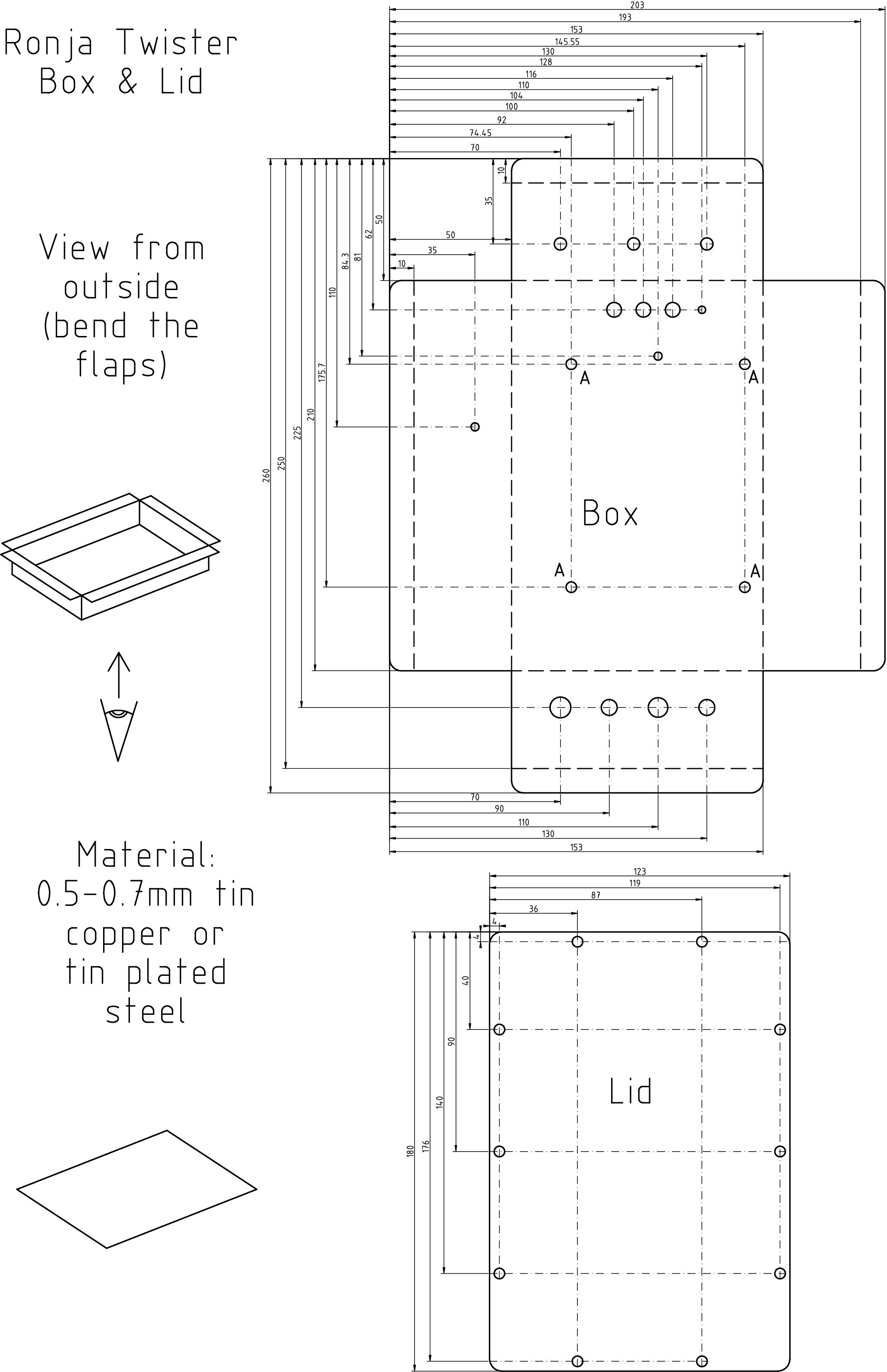
There are two possibilities how to make the box. First one is using
a calibrated printer, printing out a template and gluing the template on a tin.
The second one is measuring everything by hand. |
|
|
|
|
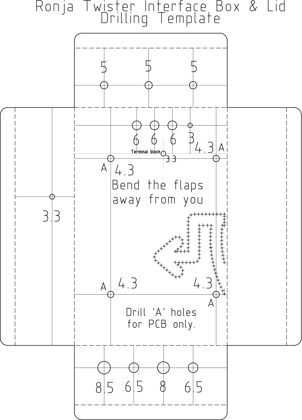
Option 1: Box body templatePrint out this template and glue on a piece of tin.![Gallery[edf]](http://images.twibright.com/tns/lvl0/edf.jpg) |
|
|
|
|
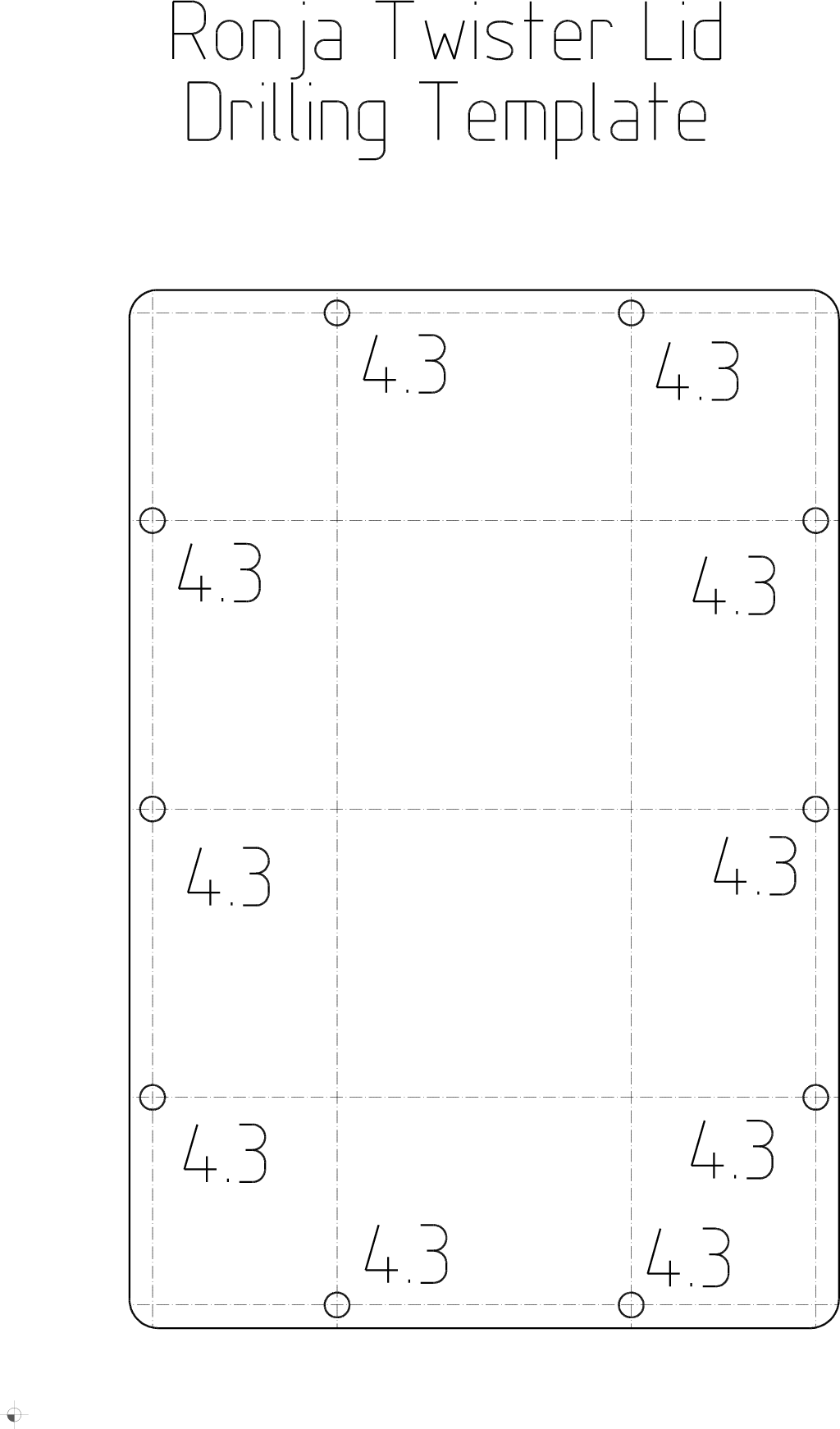
Option 1: Box lid templatePrint out this template and glue on a piece of tin. |
|
|
![Gallery[edd]](http://images.twibright.com/tns/lvl2/edd.jpg)
|
Option 1: Cutting outCut out the outline of the
templates. Use a pair of tin cutters. (Note: the photos are of obsolete template used on prototyping) ![Gallery[ede]](http://images.twibright.com/tns/lvl0/ede.jpg) |
|
|
|
|
Option 1: Drilling and bendingDrill out and bend
the box body and lid. Omit the 4 holes marked "A". Process according to the print on the template, the plan and photos: |
|
|
|
|
Option 2: making the box with manual measurementsMake the box according to the plan. Use hard stylus or thin nonporous surface marker for drawing lines. Use
square for maintaining perpendicularity and centre punch for making centres of
holes. Omit the 4 holes marked "A" |
|
|
![Gallery[ec6]](http://images.twibright.com/tns/lvl2/ec6.jpg)
|
Soldering cornersSolder corners up using
soldering iron, solder and rosin flux. If the box is made of copper, the soldering iron must be big and powerful or use two soldering irons (even they may
not suffice) or put the box on cooking stove, fire the cooking stove at appropriate power and perform the soldering on the stove. |
|
|
![Gallery[ec8]](http://images.twibright.com/tns/lvl2/ec8.jpg)
|
Lid holesMake holes on the box body by copying
them from the lid using a drill. Use 4.3mm drill bit. Use the bolts and
maybe nuts to secure the lid on already drilled holes during the operation.
Mark the lid so that you can put it back always the same way. Due to
drilling imperfections it may be difficult to close up the lid in some
other from the total 4 possible positions |
|
|
Wire through 3mm hole solderingSolder the wire into the 3mm hole. If the box is made of copper tin,
it is possible it will be impossible to solder with your soldering iron.
Either use a stronger soldering iron or two irons at once. If this is not
sufficient, place the box on a cooking stove and let the stove heat the
box and apply soldering iron on the hot box. |
|
![Gallery[ec9]](http://images.twibright.com/tns/lvl2/ec9.jpg)
|
GrommetsInstall one 6mm and three 4mm grommets.
(Note: The box on the picture is missing the hole for power connector.) |
|
|
![Gallery[eed]](http://images.twibright.com/tns/lvl2/eed.jpg)
|
Switches
Install switches. They have usually a lock against turning, use a tiny file
or a small drill to acoomodate the lock. |
|
|
|
|
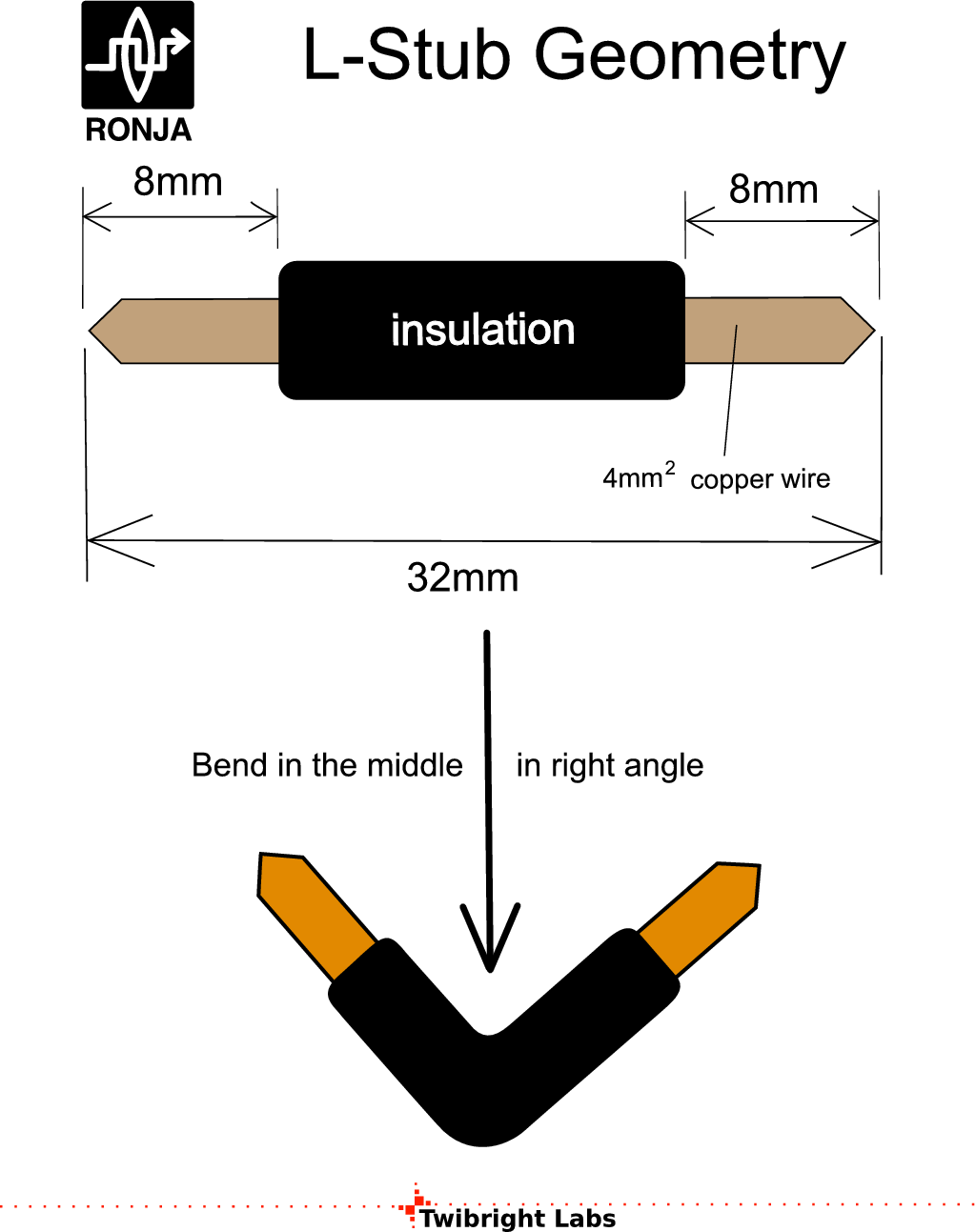
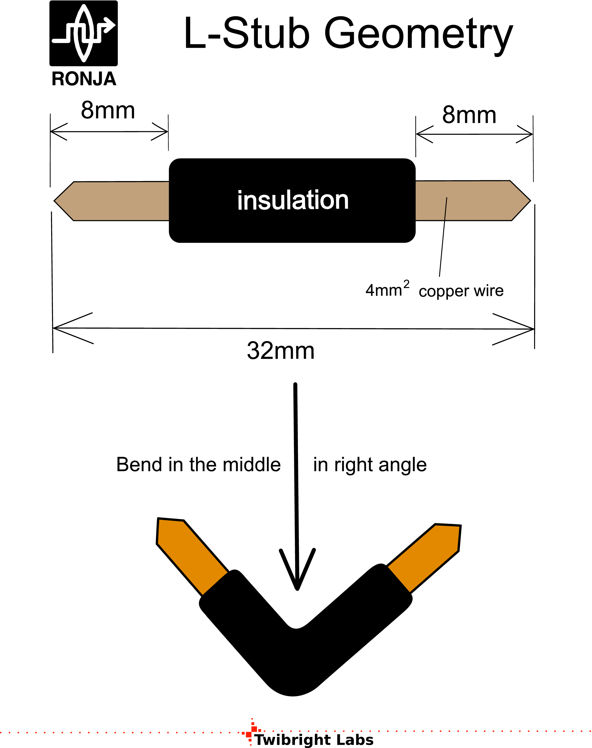
Making L stubs
Make 4 L-Stubs:
- 3 of them according to the picture
- 1 of them according to the picture but without the insulation
![Gallery[ed3]](http://images.twibright.com/tns/lvl1/ed3.jpg) |
|
|
![Gallery[ed3]](http://images.twibright.com/tns/lvl2/ed3.jpg)
|
Installing L StubsInstall 3 insulated wire stubs
into the grommets and 1 uninsulated into the 3mm hole next to the grommets
to discriminate individual terminals of the terminal block. The sidemost
terminals are unused and prevent the nut from breaking apart under mechanical
stress from the cable.![Gallery[ed3]](http://images.twibright.com/tns/lvl0/ed3.jpg) |
|
|
![Gallery[ecc]](http://images.twibright.com/tns/lvl2/ecc.jpg)
|
Mounting terminal blockMount the terminal block.
Wrench is 5.5mm. Use M3x15 bolts and M3 washers and M3 nuts and tighten. |
|
|
![Gallery[ed6]](http://images.twibright.com/tns/lvl2/ed6.jpg)
|
Color bands for CONN53Apply color bands with shown colors
made from duct tape. Remember this connector is called CONN53. |
|
|
![Gallery[ed4]](http://images.twibright.com/tns/lvl2/ed4.jpg)
|
LEDsInsert LEDs into the box in the same
order as in the picture (from left: green, yellow, red). Glue them down using
thermal glue pistol. |
|
|
![Gallery[ed8]](http://images.twibright.com/tns/lvl2/ed8.jpg)
|
STP cable: CONN52
Cut 1m of the STP cable. Crimp a RJ-45 modular jack with jacket at the end
(recommended wiring: T568B). Strip 50mm of outer insulation from the other (without jack) end of
the UTP cable. Strip 5mm from each individual wire. Put the cable through
it's grommet-equipped hole (the 6mm grommet in a group of four holes of varying
sizes). Adjust the length of unstripped cable between hole and stripped section
to 20mm. Fix up the cable in the hole using thermal glue. Seal from both sides,
using large amount of the glue. Remember this connector is called CONN52.
Note: the cable on the picture is not stranded, which is wrong.
|
|
|
|
|
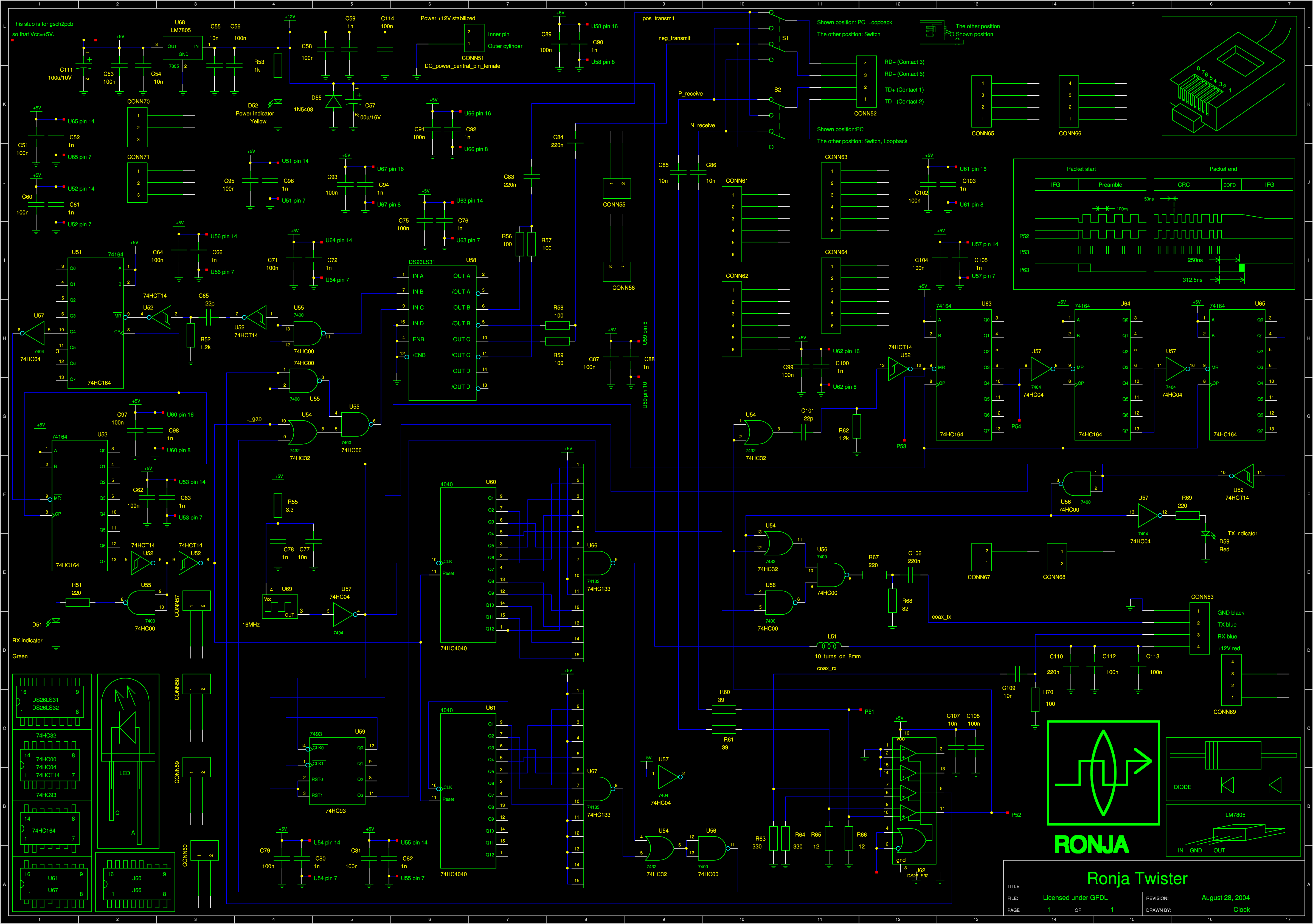
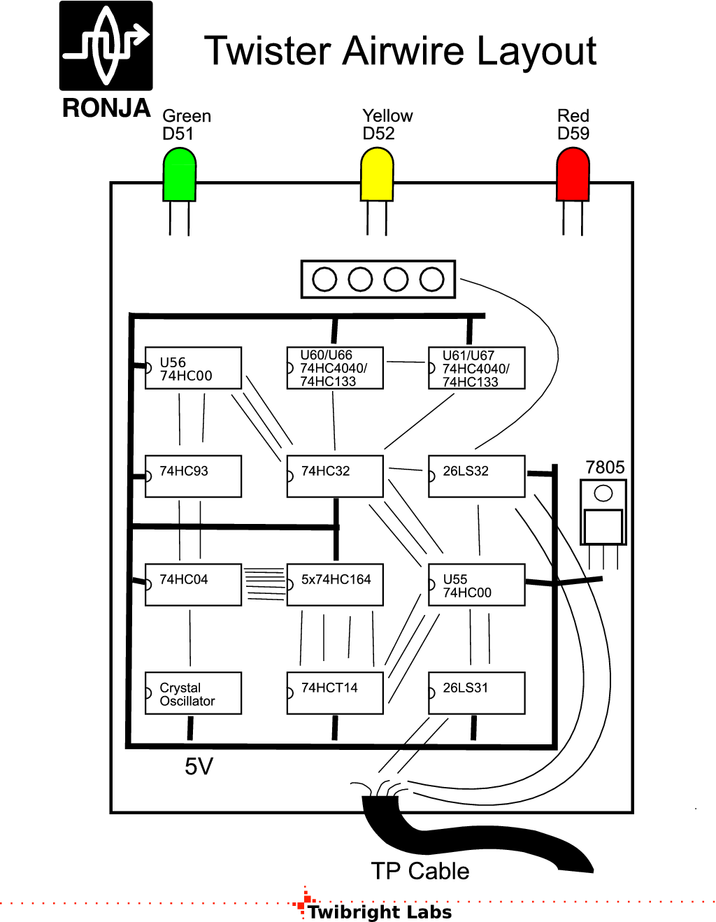
We are going to solder an airwire construction.
All IC's will be glued down on their back. The interconnections will be
soldered using a hard wire, solder and rosin flux. A transformer soldering iron
(the one with the loop) or regulated-temperature iron is used for this.
|
|
|
|
|
Preparing chips
Cut off the tips of certain IC as shown in lower left corner of the schematic |
|
|
Write on each chip's bottom side it's designation again (use paper
stickers). Glue chips down on their backs according to the placement plan.
Solder some of them on top of each other like in a stack (the uncut pins are
soldered together, the ones with cut tips are left alone):
| Number of chips in stack | Chips in stack (from bottom to top)
| | 5 | U51, U53, U64, U64, U65 (all 74HC164)
| | 2 | U66 (74HC133), U60(74HC4040)
| | 2 | U67 (74HC133), U61(74HC4040)
|
|
|
Mounting regulatorMount U68 using one short M3 bolt, one M3 toothed spring washer and one M3 nut onto it's hole from the inner side, it's pins pointing towards the four big holes (connectors & switches). |
|
|
|
Placing componentsPlace
components according to the plan. Before placing each integrated circuit, carve
the part number (for example 74HCT132) on the bottom side using sharp metal
stylus or stick a sticker and write it on. Write a refdes (e. g. U51) beside
the IC on the tin using fine-tip permanent waterproof marker. |
|
|
|
|
Soldering
Solder in all the parts according to the schematic in this order:
- All IC's
- IC blocking capacitors: C51, 52, 60, 61, 62, 63, 64, 66, 71, 72, 79, 80, 81, 82, 75, 76, 87, 88, 97, 98, 102, 103, 89, 90, 99, 100, 104, 105, 91, 92, 95, 96, 107, 108
- Other blocking capacitors: C110, 112, 58, 59, 55, 56, 53, 54, 111
- Wire and passive component interconnections within one IC case
- Inter-case connections
|
|
|
Correctness checkTake the Twister and inspect it completely.
- Left-out components
- Left-out wires
- Wires leading somewhere else
- Correct values of passive components
- Correct IC types
- Correct orientation of IC's
- Correct orientation of diodes.
- Correct orientation of polarized capacitors
- Correct orientation of connector keys
|
|
|
|
Labels
Print out the Twister label. Stick the label on the outer side of
the lid and fill in.
Print out the small schematic (see the Schematic section above)
and glue on the inner side of the lid. Cross over any component that is replaced
by an equivalent and inscribe the true equivalent type. |
|
|

 Contact, support: Clock
on the Internet Relay Chat.© 1998-2016 Karel ‘Clock’ Kulhavý et al..
Contact, support: Clock
on the Internet Relay Chat.© 1998-2016 Karel ‘Clock’ Kulhavý et al.. ![Gallery[f71]](http://images.twibright.com/tns/lvl0/f71.jpg)
![Gallery[f72]](http://images.twibright.com/tns/lvl0/f72.jpg)
![Gallery[f73]](http://images.twibright.com/tns/lvl0/f73.jpg)
![Gallery[f74]](http://images.twibright.com/tns/lvl0/f74.jpg)
![Gallery[f75]](http://images.twibright.com/tns/lvl0/f75.jpg)
![Gallery[f76]](http://images.twibright.com/tns/lvl0/f76.jpg)
![Gallery[f77]](http://images.twibright.com/tns/lvl0/f77.jpg)
![Gallery[f78]](http://images.twibright.com/tns/lvl0/f78.jpg)
![Gallery[f79]](http://images.twibright.com/tns/lvl0/f79.jpg)
![Gallery[f7a]](http://images.twibright.com/tns/lvl0/f7a.jpg)
![Gallery[f7b]](http://images.twibright.com/tns/lvl0/f7b.jpg)
![Gallery[f7c]](http://images.twibright.com/tns/lvl0/f7c.jpg)
![Gallery[f7d]](http://images.twibright.com/tns/lvl0/f7d.jpg)
![Gallery[f7e]](http://images.twibright.com/tns/lvl0/f7e.jpg)

![Gallery[ee7]](http://images.twibright.com/tns/lvl0/ee7.jpg)
![Gallery[eb9]](http://images.twibright.com/tns/lvl0/eb9.jpg)
![Gallery[ebc]](http://images.twibright.com/tns/lvl0/ebc.jpg)
![Gallery[ebd]](http://images.twibright.com/tns/lvl0/ebd.jpg)
![Gallery[ebe]](http://images.twibright.com/tns/lvl0/ebe.jpg)
![Gallery[ec0]](http://images.twibright.com/tns/lvl0/ec0.jpg)
![Gallery[ec1]](http://images.twibright.com/tns/lvl0/ec1.jpg)
![Gallery[ec2]](http://images.twibright.com/tns/lvl0/ec2.jpg)
![Gallery[ec3]](http://images.twibright.com/tns/lvl0/ec3.jpg)
![Gallery[ec4]](http://images.twibright.com/tns/lvl0/ec4.jpg)
![Gallery[eb8]](http://images.twibright.com/tns/lvl0/eb8.jpg)
![Gallery[eba]](http://images.twibright.com/tns/lvl0/eba.jpg)
![Gallery[ebb]](http://images.twibright.com/tns/lvl0/ebb.jpg)
![Gallery[ebf]](http://images.twibright.com/tns/lvl0/ebf.jpg)
![Gallery[ec5]](http://images.twibright.com/tns/lvl0/ec5.jpg)
![Gallery[ec7]](http://images.twibright.com/tns/lvl0/ec7.jpg)
![Gallery[eca]](http://images.twibright.com/tns/lvl0/eca.jpg)
![Gallery[ecb]](http://images.twibright.com/tns/lvl0/ecb.jpg)
![Gallery[ecc]](http://images.twibright.com/tns/lvl0/ecc.jpg)
![Gallery[ecd]](http://images.twibright.com/tns/lvl0/ecd.jpg)
![Gallery[ece]](http://images.twibright.com/tns/lvl0/ece.jpg)
![Gallery[ecf]](http://images.twibright.com/tns/lvl0/ecf.jpg)
![Gallery[ed0]](http://images.twibright.com/tns/lvl0/ed0.jpg)
![Gallery[ed1]](http://images.twibright.com/tns/lvl0/ed1.jpg)
![Gallery[ed2]](http://images.twibright.com/tns/lvl0/ed2.jpg)
![Gallery[eef]](http://images.twibright.com/tns/lvl0/eef.jpg)
![Gallery[ef0]](http://images.twibright.com/tns/lvl0/ef0.jpg)
![Gallery[ef1]](http://images.twibright.com/tns/lvl0/ef1.jpg)
![Gallery[ef3]](http://images.twibright.com/tns/lvl0/ef3.jpg)
![Gallery[ed7]](http://images.twibright.com/tns/lvl0/ed7.jpg)
![Gallery[ef2]](http://images.twibright.com/tns/lvl0/ef2.jpg)
![Gallery[ef4]](http://images.twibright.com/tns/lvl0/ef4.jpg)
![Gallery[ef5]](http://images.twibright.com/tns/lvl0/ef5.jpg)
![Gallery[eda]](http://images.twibright.com/tns/lvl0/eda.jpg)
![Gallery[edb]](http://images.twibright.com/tns/lvl0/edb.jpg)
![Gallery[edc]](http://images.twibright.com/tns/lvl0/edc.jpg)
