![Gallery[1261]](http://images.twibright.com/tns/lvl2/1261.jpg) |  | We are going a tubular head consisting of hollow tin tube,
two tin caps (the front one with embedded lens and heating resistors) and a tin
hood attached to the tube by bolts. | |
|
|
3D model
Slide covers, bolts and nuts are not in place in this model. |
|
|
|
|
3D cutaway model
Slide covers, bolts and nuts are not in place in this model. |
|
|
![Gallery[1cc6]](http://images.twibright.com/tns/lvl2/1cc6.jpg)
|
Cutting pipesCut (115mm+focus) long piece from the 145mm smoke pipe
using a hand saw. |
|
|
|
|
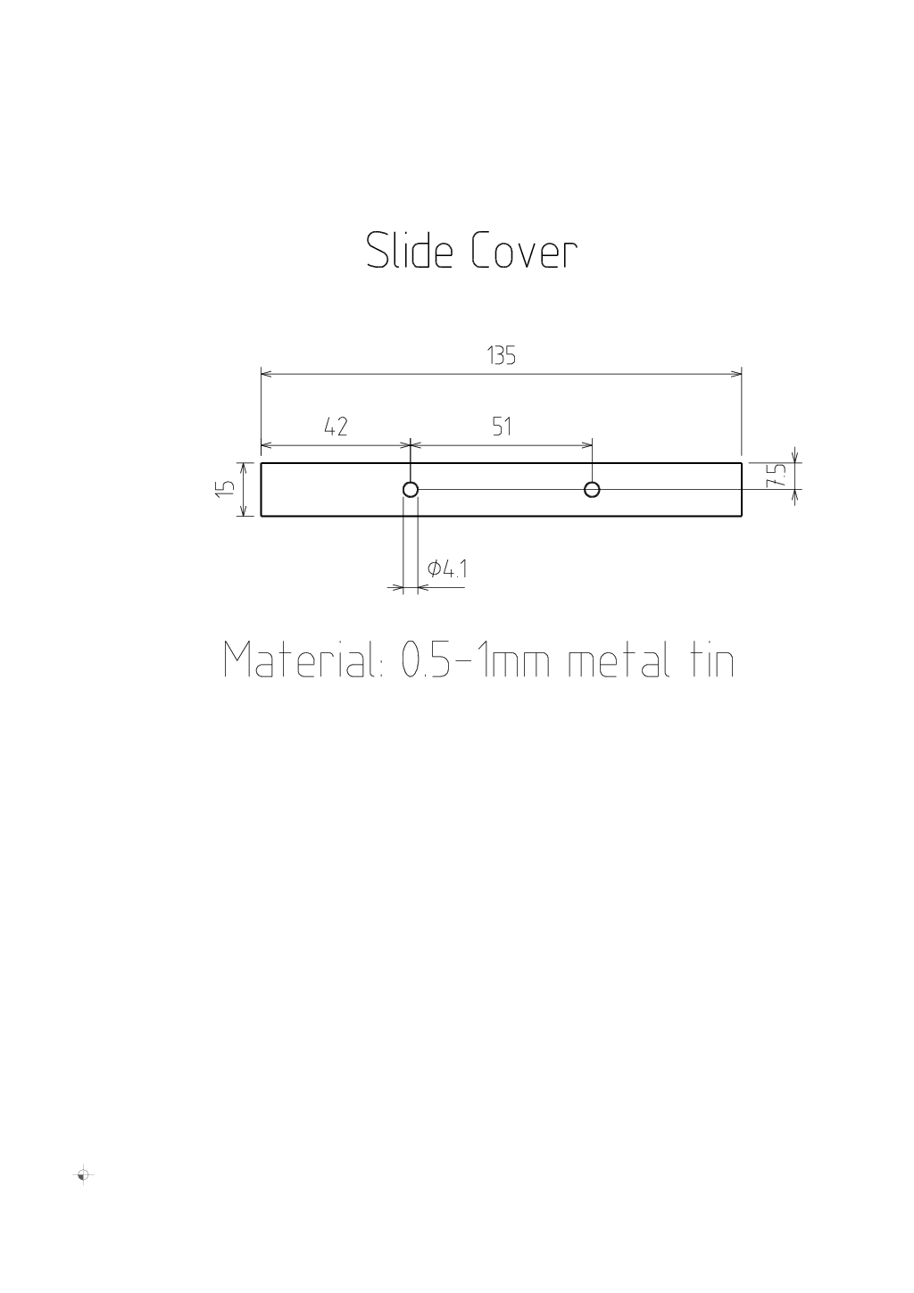
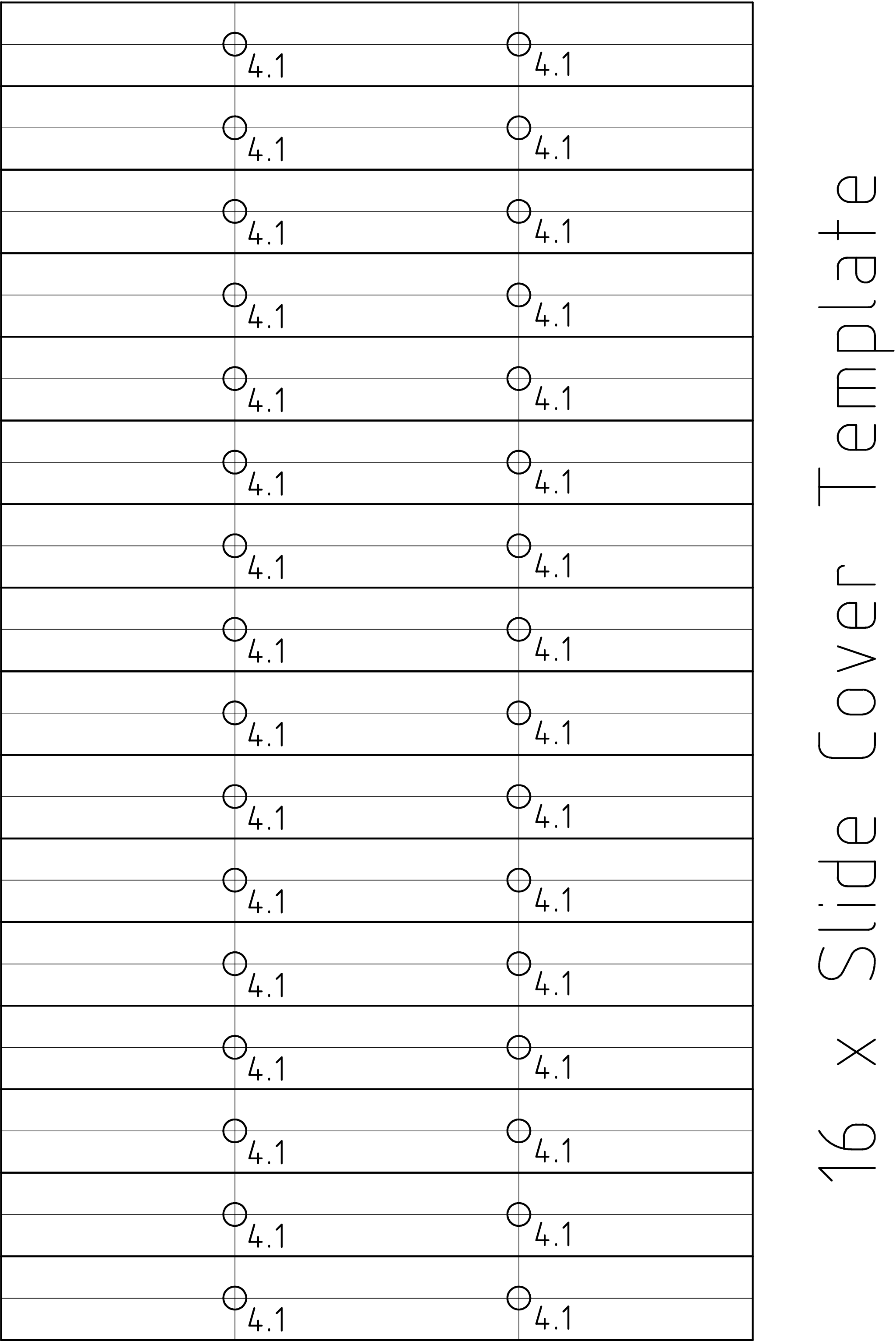
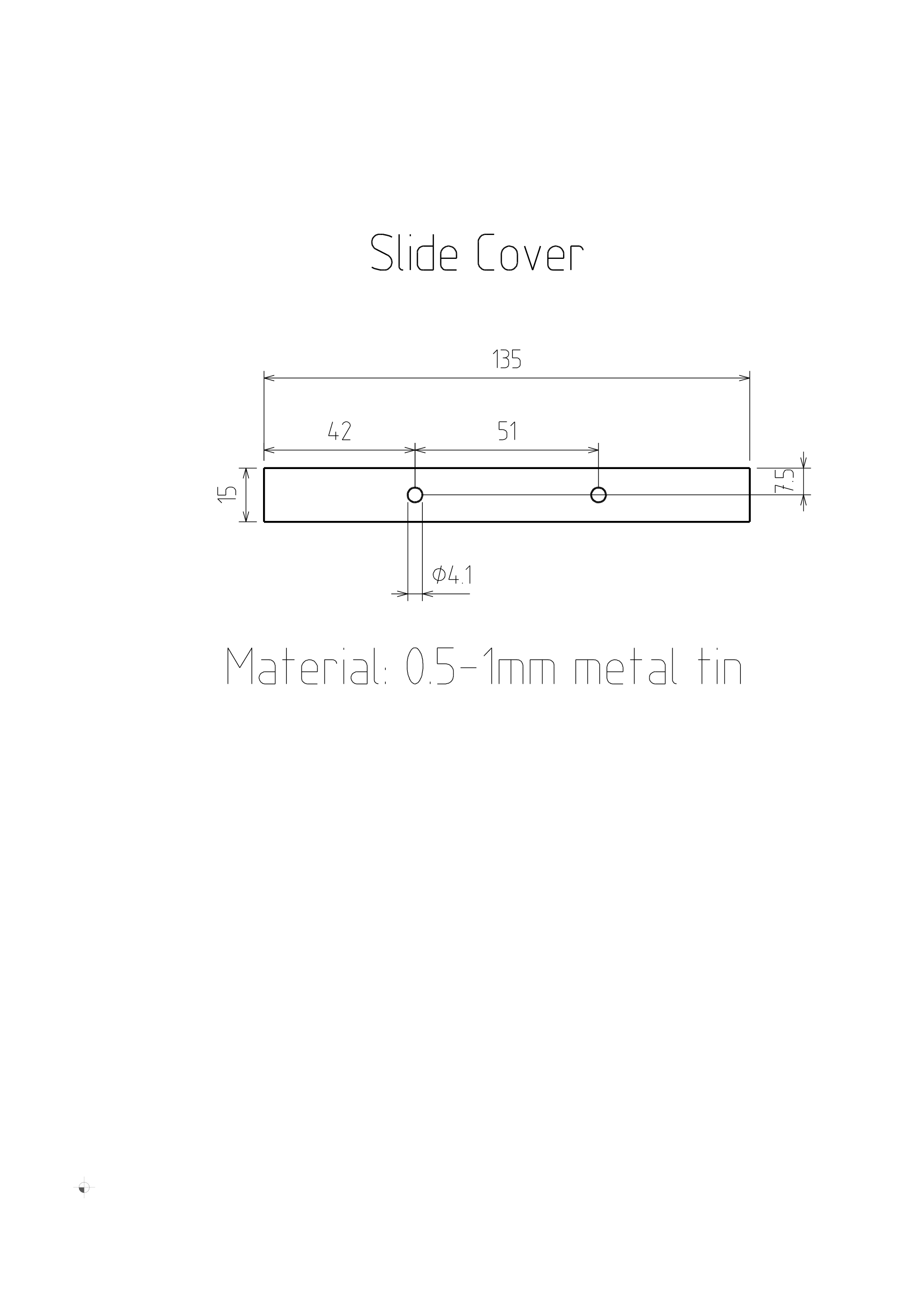
Slide cover template
If you have accurate printer, print out 2 of these 16 templates and glue on
a piece of tin for slide covers. |
|
|
|
|
Making slide coversCut and drill two slide covers |
|
|
|
|
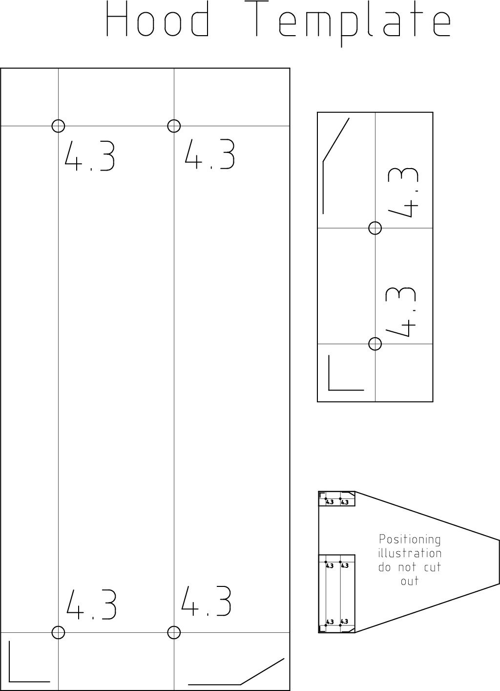
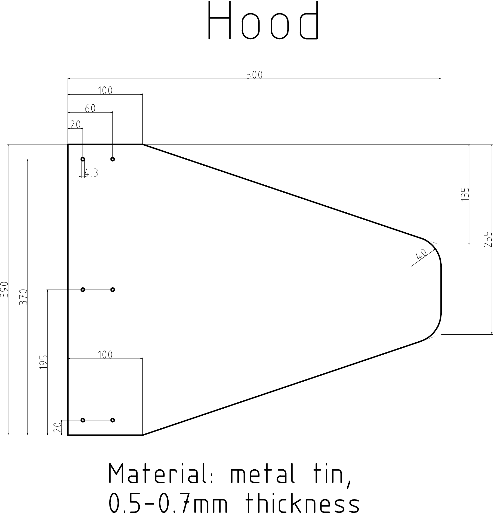
Hood template
If you have accurate printer, print this template, cut out and glue on the
hood tin (it must have precise dimension of the shorter side already). |
|
|
|
|
|
|
Making the hoodCut and drill the hood.Bend the tin into ![Gallery[56e]](http://images.twibright.com/tns/lvl2/56e.jpg) this shape (ignore the paint and bolts). this shape (ignore the paint and bolts). |
|
|
|
|
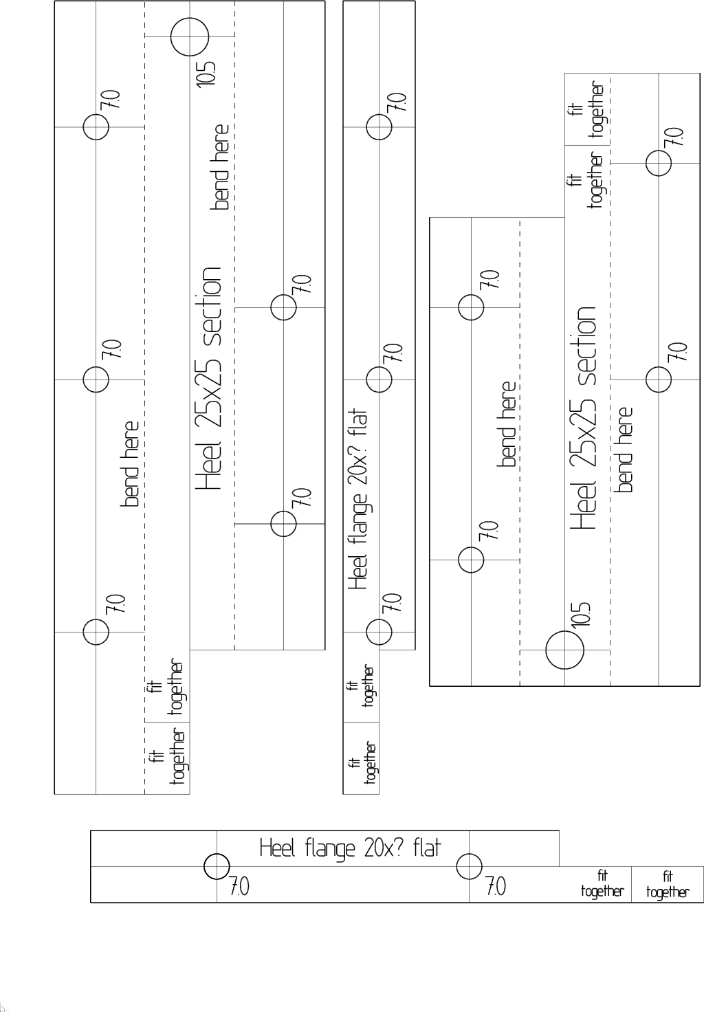
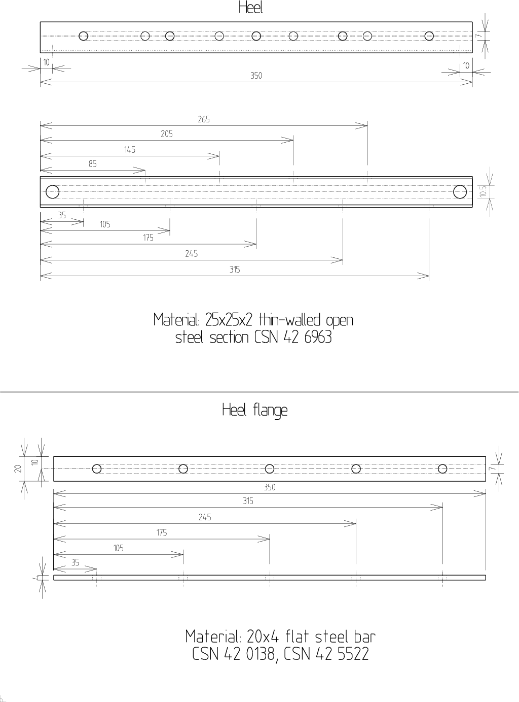
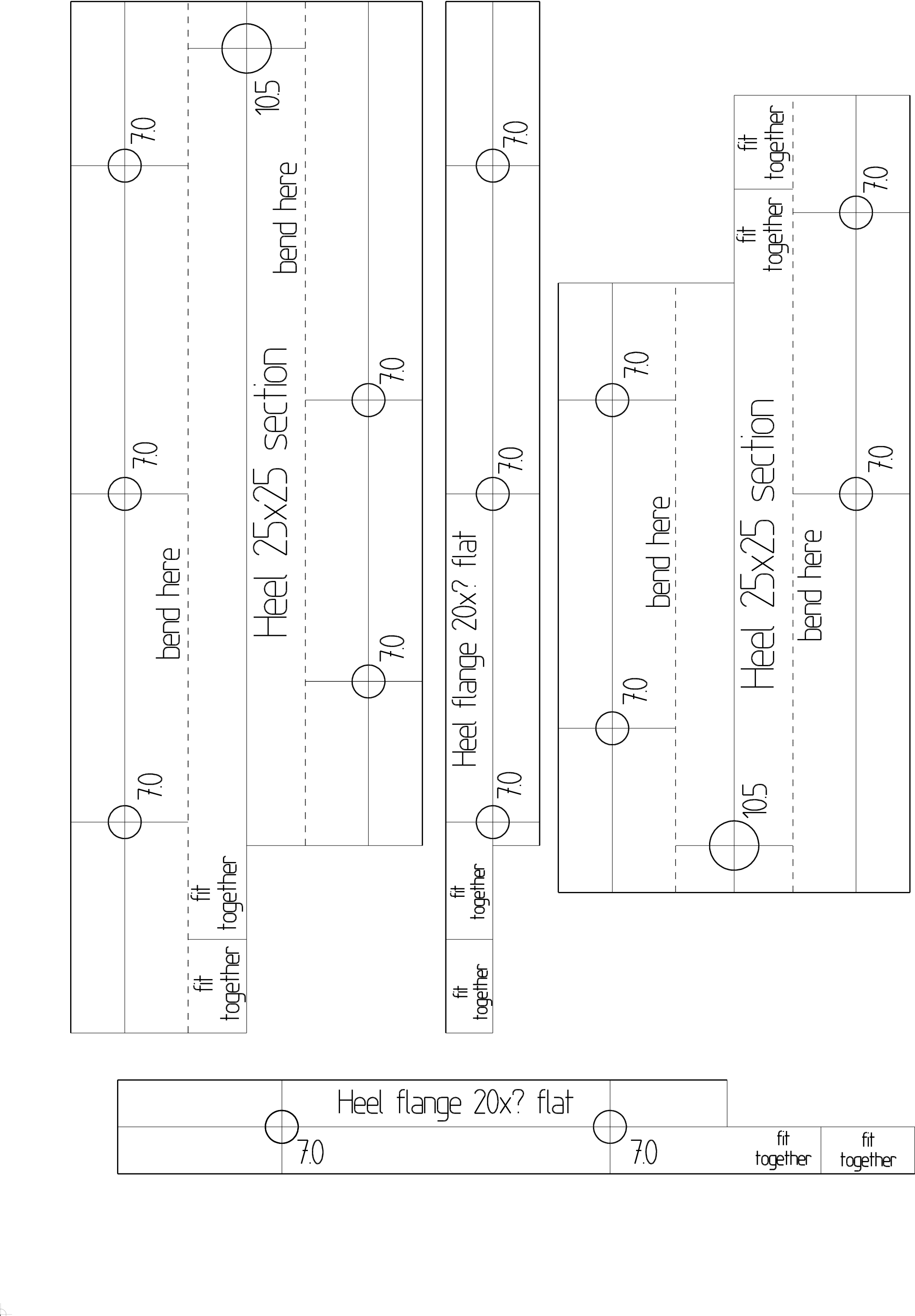
Heel template
- If you have accurate printer, print out this template and glue it on the
steel 25x25x2 U section and 20x4 flat steel bar.
- The template is from two pieces because it doesn't fit
A4 paper.
|
|
|
|
|
|
|
Making the heel and it's flangeDrill out the steel sections for the heel and heel flange |
|
|
|
|
|
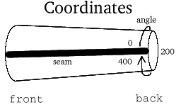
Mark the wider end of the pipe as front
and the narrower one as back. In the next, we will describe coordinates on a cylinder - by angle and
length from one edge. The angle is measured in grads, 400 grads form complete circle. |
|
|
|
|
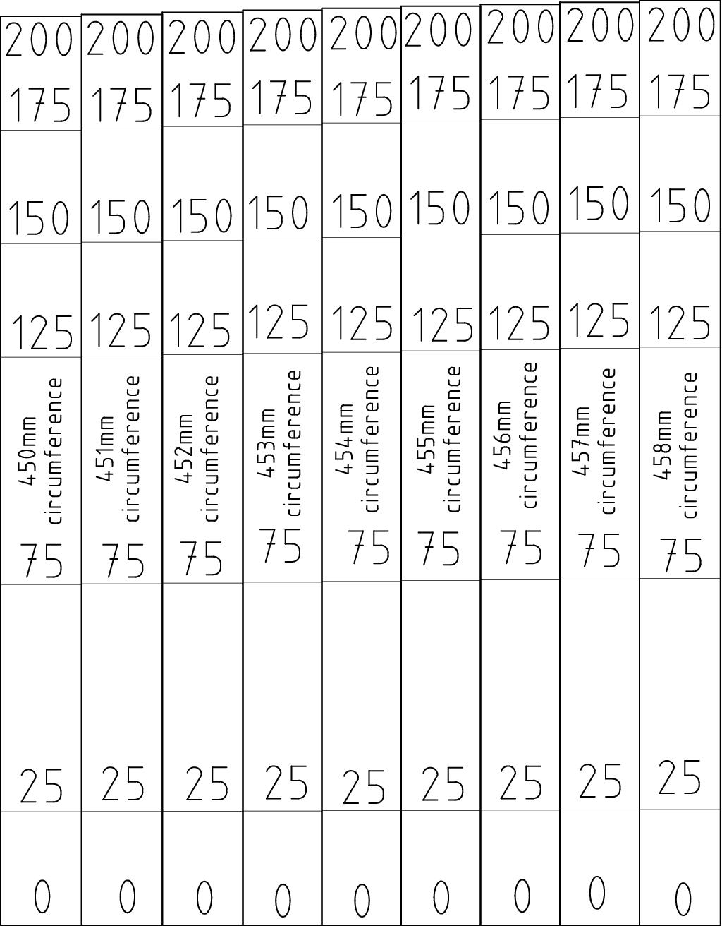
Grad gauges 450-458mm circumf.
If you have accurate printer and the pipe end has diameter from this set,
print out this gauge, cut the gauge for the pipe diameter, remember that grad
is a unit of angle where full circle is 400 grads, and skip to "Drilling
out the pipe", where you use the grad gauge to mark angles around the
pipe. |
|
|
|
|
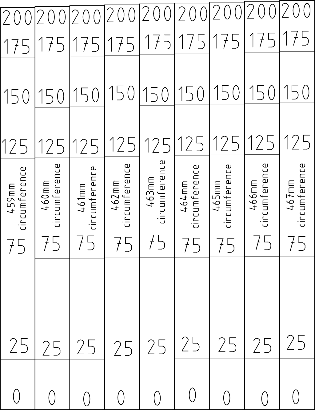
Grad gauges 459-467mm circumf.
If you have accurate printer and the pipe end has diameter from this set,
print out this gauge, cut the gauge for the pipe diameter, remember that grad
is a unit of angle where full circle is 400 grads, and skip to "Drilling
out the pipe", where you use the grad gauge to mark angles around the
pipe. |
|
|
|
|
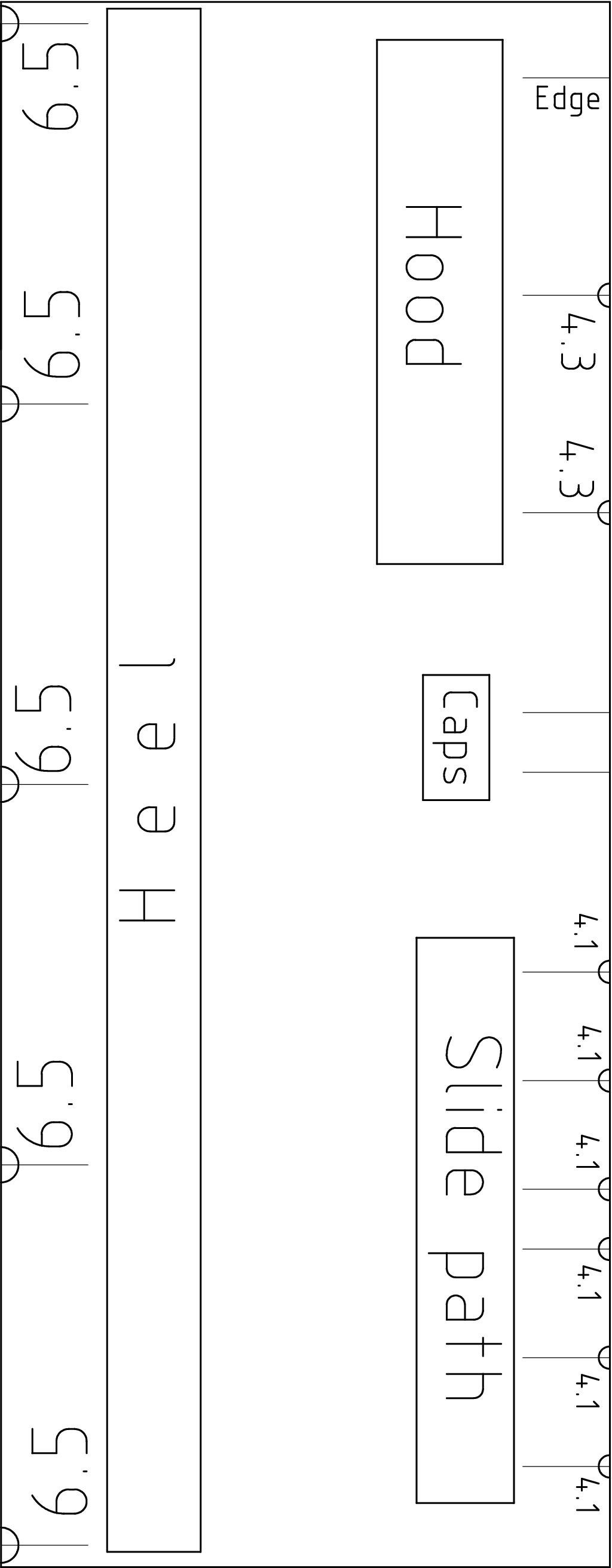
Rulers
If you have accurate printer, print out these pipe marking rulers. |
|
|
|
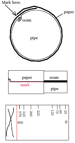
Preparing marking paper sheetUse a sheet of paper wrapped around to measure the angle.
Wrap the paper around
and make a circumference mark where the edge is. Then put the paper on
desk and divide the circumference by 400 using a calculator and make marks at 25, 75,
125, 175, 225, 250, 275, 325, and 375 times this distance. Mark them 25grad,
75grad, 125grad, 175grad, 225grad, 250grad, 275grad, 325grad, and 375grad.
Wrap the paper around the pipe again, the seam of the paper on the seam of the
tube, and copy the marks from the paper onto the tube as necessary.
![Gallery[1cd1]](http://images.twibright.com/tns/lvl2/1cd1.jpg) |
|
|
Drilling out the pipe
| Angle | Axial Offset | Hole
diameter | Purpose of the hole |
| 75grad | 11mm from front | 4.3mm | Holds
front cap |
| 175grad | 11mm from front | 4.3mm | Holds
front cap |
| 275grad | 11mm from front | 4.3mm | Holds
front cap |
| 375grad | 11mm from front | 4.3mm | Holds
front cap |
| 75grad | 11mm from back | self-cutting screw predrill diameter | Holds
rear cap |
| 175grad | 11mm from back | self-cutting screw predrill diameter | Holds
rear cap |
| 275grad | 11mm from back | self-cutting screw predrill diameter | Holds
rear cap |
| 375grad | 11mm from back | self-cutting screw predrill diameter | Holds
rear cap |
| 125grad | (focus-20mm) from front | 4.1mm |
Slide path |
| 325grad | (focus-20mm) from front | 4.1mm |
Slide path |
| 125grad, | focus from front | 4.1mm |
Slide path |
| 325grad | focus from front | 4.1mm |
Slide path |
| 125grad | (20mm+focus) from front | 4.1mm |
Slide path |
| 325grad | (20mm+focus) from front | 4.1mm |
Slide path |
| 125grad | (31mm+focus) from front | 4.1mm |
Slide path |
| 325grad | (31mm+focus) from front | 4.1mm |
Slide path |
| 125grad | (51mm+focus) from front | 4.1mm |
Slide path |
| 325grad | (51mm+focus) from front | 4.1mm |
Slide path |
| 125grad, | (71mm+focus) from front | 4.1mm |
Slide path |
| 325grad | (71mm+focus) from front | 4.1mm |
Slide path |
| 25grad | 65mm from front | 7.0mm | heel |
| 25grad | 135mm from front | 7.0mm | heel |
| 25grad | 205mm from front | 7.0mm | heel |
| 25grad | 275mm from front | 7.0mm | heel |
| 25grad | 345mm from front | 7.0mm | heel |
| 225grad | 40mm from front | 4.3mm | hood |
| 225grad | 80mm from front | 4.3mm | hood |
|
|
|
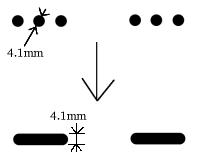
Filing out focus slide pathsConnect
holes in each group of three holes marked for future sliding path together to
form a sliding path for the screws. Use a tiny file or fret-saw to
accomplish this. You can also horizontally vice an iron bar or pipe, and chisel the paths
out against it. |
|
|
![Gallery[1d13]](http://images.twibright.com/tns/lvl2/1d13.jpg) | | 2 caps
We are going to manufacture two caps: front and rear. | |
|
|
|
|
Drilling out front cap rim
- Take one cap and mark it as front.
- Insert it into the front of the pipe, cap seam at 200 grad. If it won't
go, cut V-shaped slits into the rim at 25, 125, 225, 325 grad.
- Drill through one 4.3mm hole with 4.3mm bit. Insert some M4 bolt and drill
the hole on the opposite side. Do the remaining three holes and always insert a
bolt.
- Mark which side of the front cap is down (at the heel) with a permanent
marker. Remove the bolts and the front cap.
|
|
Drilling out rear cap rim
- Take the other cap and mark it as
rear.
- Insert it into the rear of the pipe so that cap seam is at 200 grad. If it
won't go, cut V-shaped slits into the rim at 25grad, 125grad, 225grad, 325grad.
- Drill through one self-cutting screw predrill hole and insert some pin
or nail to keep it in place. Do the remaining three holes, inserting a pin or
nail every time.
- Mark a bottom mark on the cap at the heel holes.
- Remove the pins/nails and the rear cap.
- Drill through the four holes
at the rear of the pipe with self-cutting screw through-hole diameter.
|
|
|
|
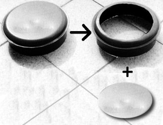
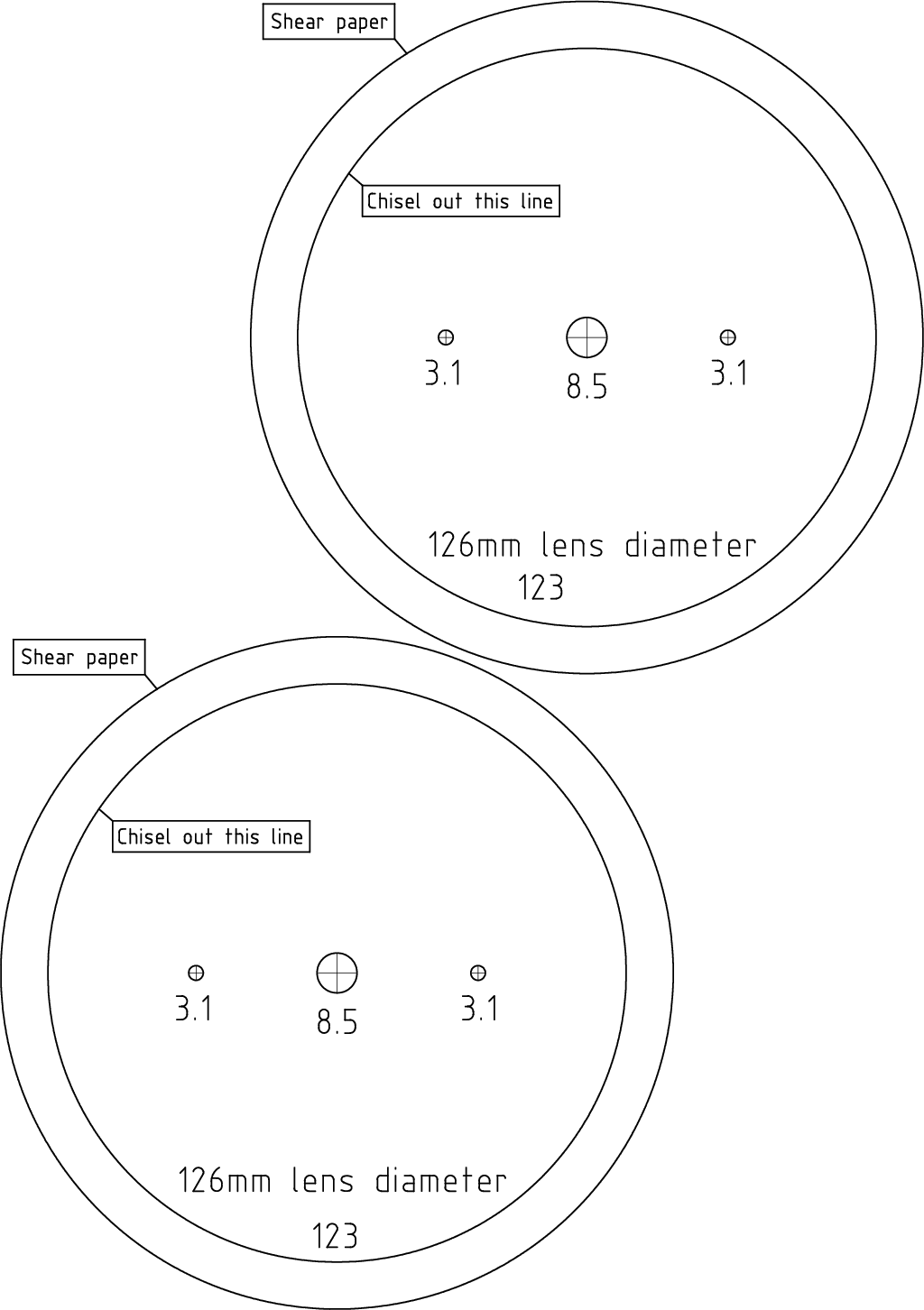
Cutting out front cap:
option 1 (template)
If you have a calibrated printer,
shear out this template. Glue the template inside the cap, with regard to
center. Put a block of wood horizontally into a vice and the cap over it
and hew out the appropriate circle using cold chisel and hammer.
Use hammer again on the wooden block to repair face of the cut.
The round
piece that falls out is called thermal shield. |
|
|
|
Cutting out front cap: option 2 (hand)Take the front cap. Make a mark in the center of the outer side using the
hard stylus and hammer. Measure exactly the lens diameter with slide gauge. Set pair of
compasses to (lens diameter/2)-1.5mm. Draw a circle. Make the circle more visible by
redrawing it using the marker pen. Put a block of wood vertically into a vice and the
cap over it, the rim down. Use cold chisel and hammer to chisel out the
curve. Then the round piece will fall out. Collect it, it will be the so
called thermal shield. Use the hammer to repair the face of the cut on the
wooden block. |
|
|
![Gallery[d5b]](http://images.twibright.com/tns/lvl2/d5b.jpg)
|
Take
the front caps and mark the inside center of them with a marker. Take a nail
and with a slight strike mark the center with it (you may even drill there a
2-3mm hole). Set the pair of compasses to (lens diameter/2)-1.5mm and draw a
circle. Mount a jig saw on the underside of a wooden board, so the blade would
come out of the top of it. Take the cap and drill 3 to 5 holes (depending on
your blade dimension) on the circumference of drawn circle. Put the cap on the
board so the blade would poke through drilled holes. Adjust the position of the
cap, so its marked center would be ortogonal to the natural path of the jig saw
on the beginning of the blade. Now take a nail and hammer it through the center
of cap deep into the wooden board. Nip off the nail header, so you can remove
the cutting (future thermal shield) easily. Turn the saw on and pivot the cap.
When the hole for the lense is complete, clean the impurities with a hand
file. |
|
|
|
|
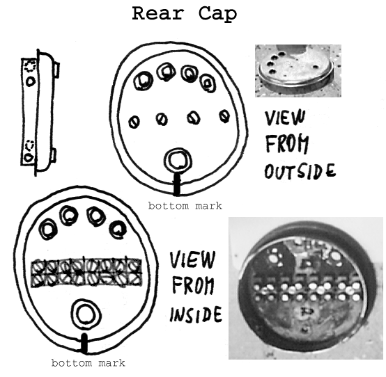
Rear Cap Template
If you have accurate printer, print out this template:
- If your terminal pitch is 9.96mm or 11.53mm instead of 10.11, use
these templates.
- You will need only one from the 2 presented
- Glue it on the inside of rear cap, with regard to the center
- Drill out and skip the next box ("Finishing rear cap drilling")
|
|
|
|
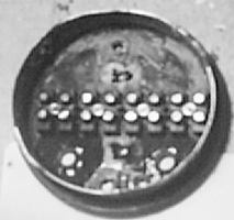
Finishing rear cap drillingPlace a 8-terminal wire nut on outer surface of the rear cap in position shown
shown in the drawing. Drill a 3.1mm hole between terminals 1 and 2, insert
an M3 bolt, drill a 3.1mm hole between terminals 7 and 8, insert a bolt,
and do another two holes between terminals 2 and 3 and terminals 4 and 5.
Drill one 8.5mm hole above the wire nut and four
10.5mm under the wire nut. |
|
|
|
|
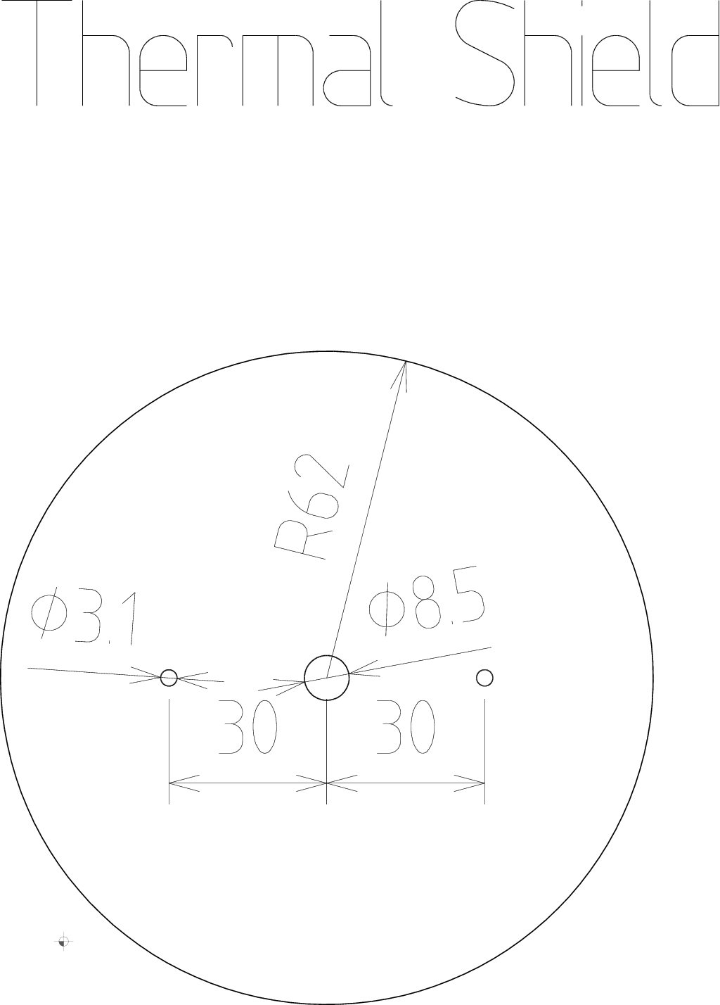
Thermal shield drilling
Drill out the thermal shield according to the drawing or template possibly glued
on the shield.
![Gallery[1c93]](http://images.twibright.com/tns/lvl1/1c93.jpg) |
|
|
|
|
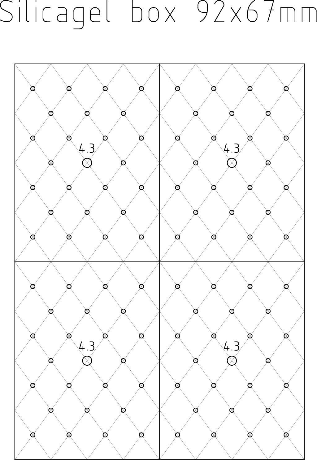
Silicagel boxes
- Print out these 4 templates, cut out and glue on 92x67mm boxes lids
(leave lids on boxes)
- Punch all unmarked holes with an awl and drill out the 4.3mm holes
|
|
|
|
|
Parts to be washed
- Pipes
- Caps (front, rear)
- Heel, heel flange
- Thermal shield
- Slide covers
- Hoods
- Lenses
|
|
|
Cleaning
- Fill a bucket with hot water and add detergent, for dosage see the bottle
label
- Throw all pieces with templates into the bucket and let the templates soak
off.
-
Use emery paper to remove noncohesive rust from pieces
where templates weren't used.
- Wash parts to be washed plus parts already in water in the bucket using
a brush or sponge to get rid of all grease
- Place everything wet on a rag and dry with hairdrier while turning
around.
- Now remove noncohesive rust from pieces where templates were used.
|
|
|
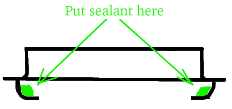
Placing the sealantPlace a fair amount of the sealant inside front cap into the
corner but not on the edge on which the lens will sit. |
|
|
|
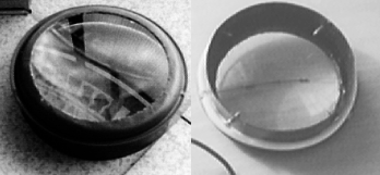
Sealing in the lensPut the lens into the place from inside the cap and shape and finish the
sealant in many gentle circular motions with your little finger so that it becomes smooth and flawless.
Take a great care not to smudge the lens.
If you have smudged the lens and decreased clear aperture, wait
until the sealant partly solidifies and then remove it mechanically and
clean the remaining haze with a rag and acetone. Removing the hardened
selalant is not easy and must be done using a razor blade, without
scratching the lens. |
|
|
|
Sealing rear cap grommetsPut cable grommets into the holes in
rear caps: 6mm grommets into 8mm
holes and 8mm grommets into 10mm holes. Seal them all against the cap from
both sides with the sillicone sealant. |
|
|
 |
WarningIf you don't seal the optical head properly, water will probably
get inside. The link may stop working and the electronics may be irreparably
destroyed. See a video. |
|
|
|
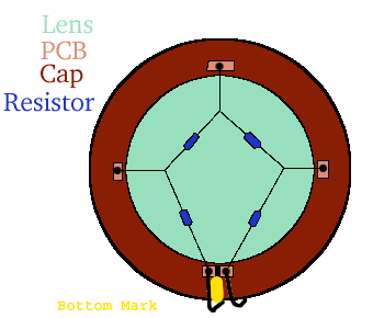
Installing heating on front cap with lens
Wait until the
sealant solidifies on front cap. Cut four small pieces of PCB blank and cut
the copper on one side of one piece into two pieces insulated by a gap.
Solder these pieces regularly on the outer rim of the lens, on the tin.
Solder the
8.2-ohm resistors there as specified in the drawing, connecting them to the rim
with pieces of thin bare wire. Check that there is no short circuit between the
network and the metallic cap itself using a multimeter. Wash the cap again with detergent,
warm water and dry them into the clean dry rag. Cut a 0.65m piece of
two-conductor 1.5mm^2 insulated cord. Solder two one-inch pieces of
4mm^2 hard copper wire on one end of the cord and insulate the solder
joints with duct tape. Solder the other end of the cord
one on the terminals of the heating network.
![Gallery[1d16]](http://images.twibright.com/tns/lvl0/1d16.jpg) |
|
|
|
|
PaintingWe are going to paint all the stuff. First look what the
painted things will approximately look like. Some parts on the photo
(rear cap outside, front cap outside) are not painted althought they should be.
|
|
|
|
|
Warning
Failure to paint the optical heads correctly can result in peeling of the
paint under the silicon sealant and water getting into the pipe, which will render
the link inoperable and destroy the electronics. See
a video. |
|
|
Primer paintingPaint with water-soluble primer. Paint only those parts of
the specified list which are able to corrode, i. e. they are from raw steel or
iron and are not galvanized nor tin-plated. Paint caps, pipes (including
inner surface), hoods,
slide covers, and thermal shields with water-soluble primer. Adhere to
manufacturer's datasheet for recommended procedure. |
|
Black painting
Paint with water-soluble matte black top coat. Paint
inner sides of the tubes, inner sides of the caps, inner sides of the
hoods, and the thermal shield. Adhere to manufacturer's datasheet for
recommended procedure. |
|
White painting
Paint all remaining surfaces that are not already black (including
those that do not corrode) with the water soluble white (matte or glossy)
top coat. Paint caps, pipes, hoods, and slide covers. Adhere to manufacturer's
datasheet for recommended procedure. |
|
Fixing holes clogged with paintPrick out paint from all
holes. |
|
|
|
Installing wire nuts
Screw the 8-terminal wire nut
into its apropriate place using the M3x15 screws, M3
nuts, and M3 washers. |
|
|
|
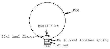
Attaching heelAttach heel to the pipe using 5 M6x14 bolts, 5 M6 (6.2mm) toothed spring washers
and 5 M6 nuts. Tighten firmly.
Seal with silicone sealant: around bolt heads, around the 20x4mm flange,
around the heel and also cover the nuts, spring washers and bolt tips.
Note: the photo is of smaller head, and of later assembly stage. |
|
|
|
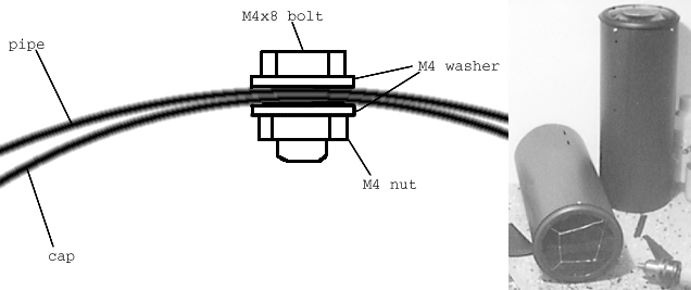
Attaching front capScrew the front cap in using 4 M4x8 bolts, 8 M4 (4.2mm) washers and 4 M4
nuts. Seal the joints from outside with silicone sealant. Seal the gap between
the pipe and the cap with silicone sealant from outside. |
|
|
|
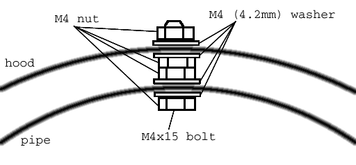
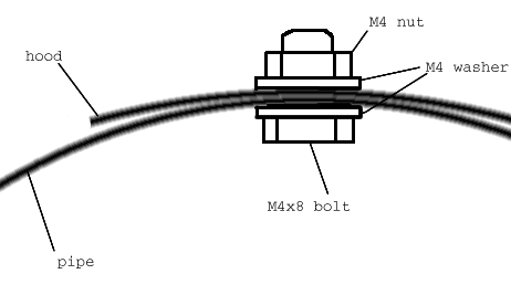
Attaching hood at it's centreMount the hood's central two holes
on two holes on the top of the pipe using 2 M4x15 bolts, 8 M4 (4.2mm) washers,
and 6 M4 nuts. Tighten firmly. Seal the joints from inner side carefully with silicone sealant. Press the hood against the pipe
firmly and drill through the remaining holes on the hood with 4.3mm
bit. |
|
|
|
Attaching hood's sidesMount the hood sides using 4 M4x8 bolts, 8 M4 (4.2mm) washers, and 4 M4 nuts. Tighten firmly.
Seal the joints both from inner and outer side with silicone sealant. Put also
some sealant between the tins before you assemble them together. |
|
|
Preparing silica gel
- Put the
silica gel into the two boxes (200g fits into two 92x67 boxes and
100g into two 67x46 boxes). Screw up using M4x25 countersink head bolts
and double M4 nut. Tighten the nuts one against the other.
- If the silicagel is not 100% dry (usually shipped in airtight
containers), put the bag into oven (at minimum heat) for two hours. Gas oven
to minimum setting, electric to 150degC. Do not use microwave oven. If you
were so stupid you bought the blue one, be sure not to do that in a kitchenware
and destroy the vessel safely after usage because it will be contaminated by
the cancerogenous dust. Store the dry silica gel boxes in airtight jars or
plastic bags.
|
|
Grinding paint off positioning-critical jointsUse emery
paper to grind off the paint from around the six holes on the heel.![Gallery[13db]](http://images.twibright.com/tns/lvl1/13db.jpg) |
|
|
|
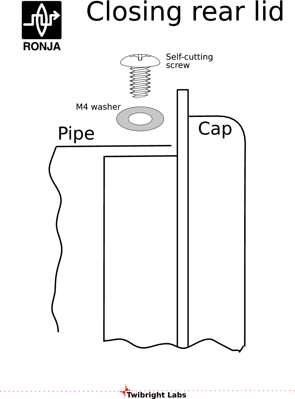
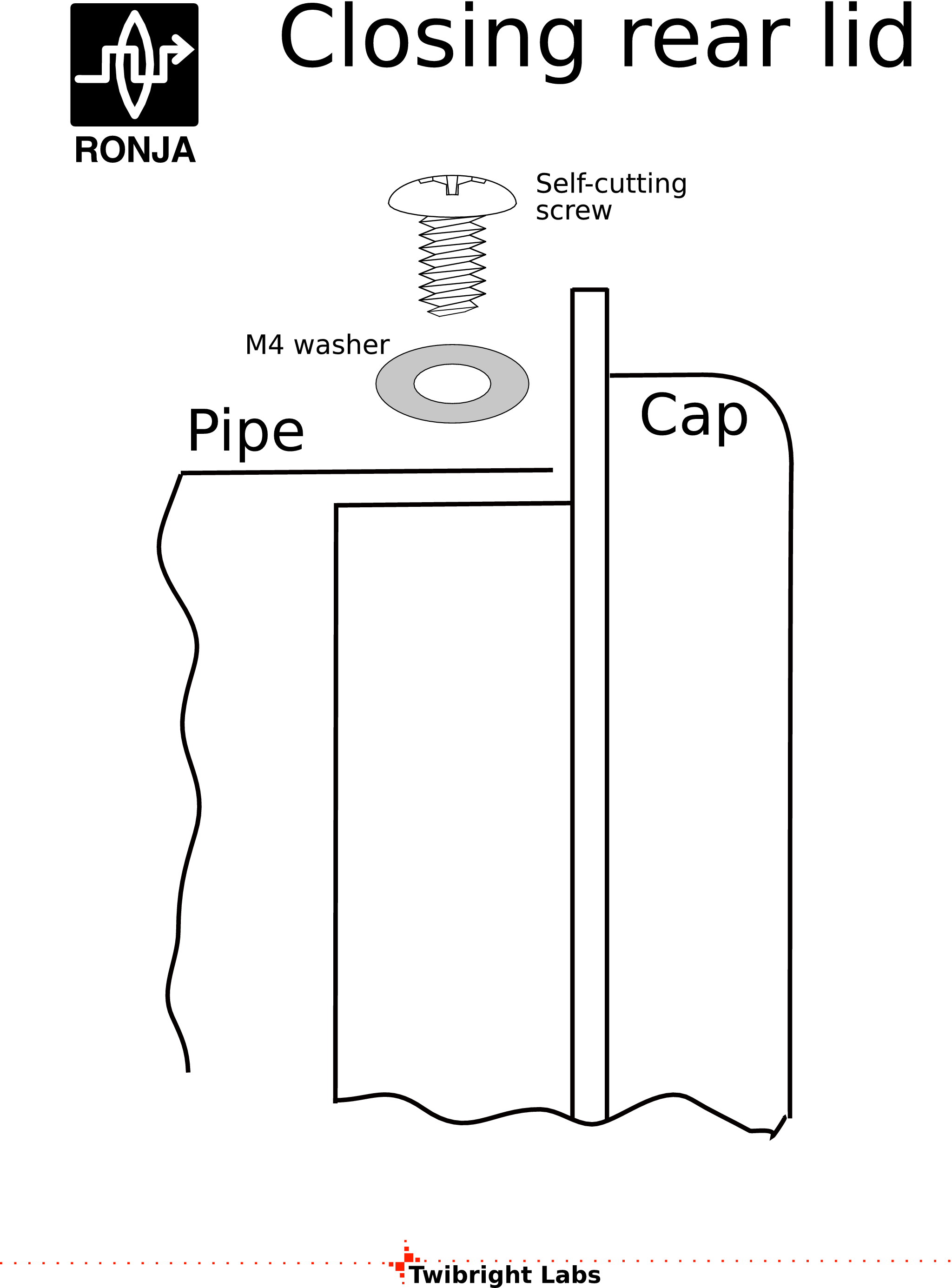
Save for future
Save the slide covers and 4 self-cutting screws and 4 M4 washers
for mounting electronics inside and closing the rear cap. The washers should be put under
heads of the screws. |
|
|

 Contact, support: Clock
on the Internet Relay Chat.© 1998-2016 Karel ‘Clock’ Kulhavý et al..
Contact, support: Clock
on the Internet Relay Chat.© 1998-2016 Karel ‘Clock’ Kulhavý et al.. ![3d/head [0]](/3d/head_0.png)
![3d/head [1]](/3d/head_1.png)
![3d/head [2]](/3d/head_2.png)
![3d/head [3]](/3d/head_3.png)
![3d/head [4]](/3d/head_4.png)

![3d/headcut [0]](/3d/headcut_0.png)
![3d/headcut [1]](/3d/headcut_1.png)
![3d/headcut [2]](/3d/headcut_2.png)
![3d/headcut [3]](/3d/headcut_3.png)
![3d/headcut [4]](/3d/headcut_4.png)

![Gallery[1cc8]](http://images.twibright.com/tns/lvl1/1cc8.jpg)
![Gallery[1cc7]](http://images.twibright.com/tns/lvl1/1cc7.jpg)

![Gallery[e4]](http://images.twibright.com/tns/lvl0/e4.jpg)
![Gallery[e5]](http://images.twibright.com/tns/lvl0/e5.jpg)
![Gallery[e6]](http://images.twibright.com/tns/lvl0/e6.jpg)
![Gallery[1ccf]](http://images.twibright.com/tns/lvl2/1ccf.jpg)
![Gallery[1cd0]](http://images.twibright.com/tns/lvl2/1cd0.jpg)
![3d/hood [0]](/3d/hood_0.png)
![3d/hood [1]](/3d/hood_1.png)
![3d/hood [2]](/3d/hood_2.png)
![3d/hood [3]](/3d/hood_3.png)
![3d/hood [4]](/3d/hood_4.png)


![Gallery[1cc9]](http://images.twibright.com/tns/lvl0/1cc9.jpg)
![Gallery[1cca]](http://images.twibright.com/tns/lvl0/1cca.jpg)
![Gallery[1ccb]](http://images.twibright.com/tns/lvl0/1ccb.jpg)
![Gallery[1ccc]](http://images.twibright.com/tns/lvl0/1ccc.jpg)
![Gallery[1c96]](http://images.twibright.com/tns/lvl1/1c96.jpg)
![Gallery[1c99]](http://images.twibright.com/tns/lvl1/1c99.jpg)
![Gallery[1c97]](http://images.twibright.com/tns/lvl1/1c97.jpg)
![3d/heel [0]](/3d/heel_0.png)
![3d/heel [1]](/3d/heel_1.png)
![3d/heel [2]](/3d/heel_2.png)
![3d/heel [3]](/3d/heel_3.png)
![3d/heel [4]](/3d/heel_4.png)

![Gallery[1c9b]](http://images.twibright.com/tns/lvl1/1c9b.jpg)
![Gallery[1c9c]](http://images.twibright.com/tns/lvl1/1c9c.jpg)
![Gallery[1c9d]](http://images.twibright.com/tns/lvl1/1c9d.jpg)
![Gallery[1c9a]](http://images.twibright.com/tns/lvl1/1c9a.jpg)
![3d/pipe [0]](/3d/pipe_0.png)
![3d/pipe [1]](/3d/pipe_1.png)
![3d/pipe [2]](/3d/pipe_2.png)
![3d/pipe [3]](/3d/pipe_3.png)
![3d/pipe [4]](/3d/pipe_4.png)

![Gallery[1cd2]](http://images.twibright.com/tns/lvl1/1cd2.jpg)
![Gallery[1cd3]](http://images.twibright.com/tns/lvl1/1cd3.jpg)
![Gallery[1cd4]](http://images.twibright.com/tns/lvl1/1cd4.jpg)
![Gallery[18c4]](http://images.twibright.com/tns/lvl1/18c4.jpg)
![Gallery[18c5]](http://images.twibright.com/tns/lvl1/18c5.jpg)
![Gallery[18c6]](http://images.twibright.com/tns/lvl1/18c6.jpg)
![Gallery[18c7]](http://images.twibright.com/tns/lvl1/18c7.jpg)
![Gallery[d2]](http://images.twibright.com/tns/lvl0/d2.jpg)
![Gallery[d3]](http://images.twibright.com/tns/lvl0/d3.jpg)
![Gallery[d4]](http://images.twibright.com/tns/lvl0/d4.jpg)
![Gallery[d1]](http://images.twibright.com/tns/lvl0/d1.jpg)
![Gallery[1c95]](http://images.twibright.com/tns/lvl1/1c95.jpg)
![Gallery[1cce]](http://images.twibright.com/tns/lvl1/1cce.jpg)
![Gallery[1ccd]](http://images.twibright.com/tns/lvl1/1ccd.jpg)
![3d/front_cap [0]](/3d/front_cap_0.png)
![3d/front_cap [1]](/3d/front_cap_1.png)
![3d/front_cap [2]](/3d/front_cap_2.png)
![3d/front_cap [3]](/3d/front_cap_3.png)
![3d/front_cap [4]](/3d/front_cap_4.png)

![3d/rear_cap [0]](/3d/rear_cap_0.png)
![3d/rear_cap [1]](/3d/rear_cap_1.png)
![3d/rear_cap [2]](/3d/rear_cap_2.png)
![3d/rear_cap [3]](/3d/rear_cap_3.png)
![3d/rear_cap [4]](/3d/rear_cap_4.png)

![Gallery[de]](http://images.twibright.com/tns/lvl0/de.jpg)
![Gallery[df]](http://images.twibright.com/tns/lvl0/df.jpg)
![Gallery[e0]](http://images.twibright.com/tns/lvl0/e0.jpg)
![Gallery[e1]](http://images.twibright.com/tns/lvl0/e1.jpg)
![Gallery[e2]](http://images.twibright.com/tns/lvl0/e2.jpg)
![Gallery[e3]](http://images.twibright.com/tns/lvl0/e3.jpg)
![Gallery[1c8f]](http://images.twibright.com/tns/lvl1/1c8f.jpg)
![Gallery[1c90]](http://images.twibright.com/tns/lvl1/1c90.jpg)
![Gallery[1c91]](http://images.twibright.com/tns/lvl1/1c91.jpg)
![Gallery[1d11]](http://images.twibright.com/tns/lvl1/1d11.jpg)
![Gallery[d5d]](http://images.twibright.com/tns/lvl0/d5d.jpg)
![Gallery[d5f]](http://images.twibright.com/tns/lvl0/d5f.jpg)
![Gallery[d62]](http://images.twibright.com/tns/lvl0/d62.jpg)
![Gallery[1d11]](http://images.twibright.com/tns/lvl0/1d11.jpg)
![Gallery[1c93]](http://images.twibright.com/tns/lvl0/1c93.jpg)

![Gallery[1163]](http://images.twibright.com/tns/lvl1/1163.jpg)
![Gallery[1164]](http://images.twibright.com/tns/lvl1/1164.jpg)
![Gallery[1165]](http://images.twibright.com/tns/lvl1/1165.jpg)
![Gallery[1c9f]](http://images.twibright.com/tns/lvl1/1c9f.jpg)
![Gallery[1cba]](http://images.twibright.com/tns/lvl0/1cba.jpg)
![Gallery[1cbb]](http://images.twibright.com/tns/lvl0/1cbb.jpg)
![Gallery[1cbc]](http://images.twibright.com/tns/lvl0/1cbc.jpg)
![Gallery[1ca5]](http://images.twibright.com/tns/lvl0/1ca5.jpg)
![Gallery[1ca6]](http://images.twibright.com/tns/lvl0/1ca6.jpg)
![Gallery[1ca7]](http://images.twibright.com/tns/lvl0/1ca7.jpg)
![Gallery[1d07]](http://images.twibright.com/tns/lvl0/1d07.jpg)
![Gallery[131f]](http://images.twibright.com/tns/lvl0/131f.jpg)
![Gallery[1ca8]](http://images.twibright.com/tns/lvl0/1ca8.jpg)
![Gallery[1ca9]](http://images.twibright.com/tns/lvl0/1ca9.jpg)
![Gallery[1caa]](http://images.twibright.com/tns/lvl0/1caa.jpg)
![Gallery[1cac]](http://images.twibright.com/tns/lvl0/1cac.jpg)
![Gallery[1cad]](http://images.twibright.com/tns/lvl0/1cad.jpg)
![Gallery[1cb6]](http://images.twibright.com/tns/lvl0/1cb6.jpg)
![Gallery[1cb7]](http://images.twibright.com/tns/lvl0/1cb7.jpg)
![Gallery[1cb8]](http://images.twibright.com/tns/lvl0/1cb8.jpg)
![Gallery[1cb9]](http://images.twibright.com/tns/lvl0/1cb9.jpg)
![Gallery[1cbd]](http://images.twibright.com/tns/lvl0/1cbd.jpg)
![Gallery[c5]](http://images.twibright.com/tns/lvl0/c5.jpg)
![Gallery[c6]](http://images.twibright.com/tns/lvl0/c6.jpg)
![Gallery[c7]](http://images.twibright.com/tns/lvl0/c7.jpg)
![Gallery[c8]](http://images.twibright.com/tns/lvl0/c8.jpg)
![Gallery[c9]](http://images.twibright.com/tns/lvl0/c9.jpg)
![Gallery[ca]](http://images.twibright.com/tns/lvl0/ca.jpg)
![Gallery[cb]](http://images.twibright.com/tns/lvl0/cb.jpg)
![Gallery[ec]](http://images.twibright.com/tns/lvl0/ec.jpg)
![Gallery[ed]](http://images.twibright.com/tns/lvl0/ed.jpg)
![Gallery[ee]](http://images.twibright.com/tns/lvl0/ee.jpg)
![Gallery[ef]](http://images.twibright.com/tns/lvl0/ef.jpg)
![Gallery[f0]](http://images.twibright.com/tns/lvl0/f0.jpg)
![Gallery[f1]](http://images.twibright.com/tns/lvl0/f1.jpg)
![Gallery[1ca1]](http://images.twibright.com/tns/lvl0/1ca1.jpg)
![Gallery[1ca2]](http://images.twibright.com/tns/lvl0/1ca2.jpg)
![Gallery[1ca3]](http://images.twibright.com/tns/lvl0/1ca3.jpg)
![Gallery[1ca4]](http://images.twibright.com/tns/lvl0/1ca4.jpg)
![Gallery[13da]](http://images.twibright.com/tns/lvl0/13da.jpg)
![Gallery[13db]](http://images.twibright.com/tns/lvl0/13db.jpg)
![Gallery[13dc]](http://images.twibright.com/tns/lvl0/13dc.jpg)
![Gallery[13df]](http://images.twibright.com/tns/lvl0/13df.jpg)
![Gallery[13e0]](http://images.twibright.com/tns/lvl0/13e0.jpg)
![Gallery[13de]](http://images.twibright.com/tns/lvl1/13de.jpg)
![Gallery[13e2]](http://images.twibright.com/tns/lvl1/13e2.jpg)
![Gallery[13da]](http://images.twibright.com/tns/lvl1/13da.jpg)
![Gallery[13dc]](http://images.twibright.com/tns/lvl1/13dc.jpg)
![Gallery[13df]](http://images.twibright.com/tns/lvl1/13df.jpg)
![Gallery[1caf]](http://images.twibright.com/tns/lvl1/1caf.jpg)
![Gallery[1cc0]](http://images.twibright.com/tns/lvl1/1cc0.jpg)
![Gallery[1cc1]](http://images.twibright.com/tns/lvl1/1cc1.jpg)
![Gallery[1cc3]](http://images.twibright.com/tns/lvl1/1cc3.jpg)
![Gallery[1cc2]](http://images.twibright.com/tns/lvl1/1cc2.jpg)
![Gallery[1cbe]](http://images.twibright.com/tns/lvl1/1cbe.jpg)
![Gallery[1cbf]](http://images.twibright.com/tns/lvl1/1cbf.jpg)
![Gallery[1cc4]](http://images.twibright.com/tns/lvl1/1cc4.jpg)