 |
We are going to test the electronics. You should get to the
end without
problems. If there is a bug and you can't identify it and repair it, ask on the
mailing list. |
|
|
|
Plug AUI Forte alone (without RX and TX) into the AUI network card.
The yellow light
should shine. If it shines dimly or doesn't shine then there's a short
circuit on the power: in such case disconnect it immediately and check the circuit again.
You can also measure the power consumption of the AUI Forte by
unsoldering the power wire inside and sticking ampermeter probe into the
resulting gap. The typical value is 160mA.
The red light shall not shine even not dimly. If it shines, there is a
bug in the transmitter path logic. Check the topology and component values again. |
|
|
|
|
|
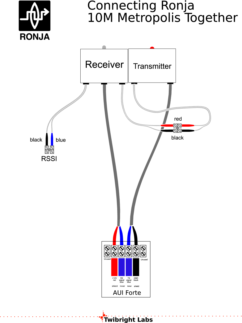
Powering Metropolis for the first
time
Now disconnect AUI Forte from the network card and connect receiver and transmitter
according to the picture. Plug the AUI Forte back into the network
card. Again check the yellow
light and you may also check the total consumption: it should be max.
300mA.
|
|
|
Check of measurement points
Check all voltage measurement points except current one, because for
measuring a current you have to break the circuit. Measurement points are those
small tables in the schematics with various variables. Check the values in all
three boxes: Twister, Receiver, Transmitter. Determine if the measured voltages
are in the specified range. The voltages are measured against ground (i. e.
the tin of the can). The values should be all OK. If they are not, perform
correctness checks of the affected module once more. If the problem
still persists, ask on the mailing list. |
|
Testing RSSI operation
Check whether the TX diode shines. Connect 200mV voltmeter into Receiver's
RX level DC measurement (Received Signal Strength Indicator, RSSI). Check
whether the multimeter readout reacts to the light strength from the
transmitter. |
|
Preemphasis setting
- Do preemphasis test of Metropolis.
- Change value of R8 according to the result:
| Result | Action
|
|---|
| LED shines too long | Increase R8
| | LED shines too short | Decrease R8
| | OK | Done
|
|
|
LED current setting
Let the transmitter shine without sending any packets into it. Measure DC
voltage across R11 (default value 8.2 Ohm) and then switch off the transmitter
completely by plugging the AUI Forte out of NIC. Measure the real value of the
R11 (default nominal value 8.2 Ohm). Compute the DC current flowing according to
Ohm's law as I=U/R. If it is greater than 68mA, replace R11 (8R2) with R14
(10 Ohm). Reconnect the power of AUI Forte and continue with testing by sending
ping's. |
|
|
Do at least one from the following Metropolis tests (if you don't have prerequisites
for one, then go to another etc.):
|
|
If something is wrong
If you are getting substantially smaller ranges (for example 0.7m for
SFH203), something is wrong.
The input transistor of the receiver (Q101, BF908 or its equivalent) can be
broken-through. It is caused by inappropriate handling: the device is static
electricity sensitive. It can be caused also by soldering with an iron with
ungrounded tip or transformer soldering gun can generate spikes during
switching. This sometimes manifests as a voltage greater than 0V on P103. My
healthy receiver has 0.1mV on P103.
A breakthrough of G2 sometimes manifests itself as a receiver that is
oscillating (doesn't work at all or has inferior range) where the oscillations
cease when C103 is removed from the circuit.
Breakthrough of Q101 can be fixed only by replacing with another one and
obeying the rules for manipulation with static electricity sensitive devices.
|
|
Range reduction
If you plan to use Ronja on a link less than 1/4 of nominal distance,
then perform range reduction now. |
|
![Gallery[414]](http://images.twibright.com/tns/lvl2/414.jpg)
|
Mount Thermal Shields
Now mount the thermal shields to both the receiver and transmitter
using four M3x10 screws and 12 M3 nuts. Tighten it all together firmly. |
|
|
![Gallery[69c]](http://images.twibright.com/tns/lvl1/69c.jpg)
![Gallery[9b]](http://images.twibright.com/tns/lvl1/9b.jpg)
![Gallery[9e]](http://images.twibright.com/tns/lvl1/9e.jpg)

 Contact, support: Clock
on the Internet Relay Chat.© 1998-2016 Karel ‘Clock’ Kulhavý et al..
Contact, support: Clock
on the Internet Relay Chat.© 1998-2016 Karel ‘Clock’ Kulhavý et al.. 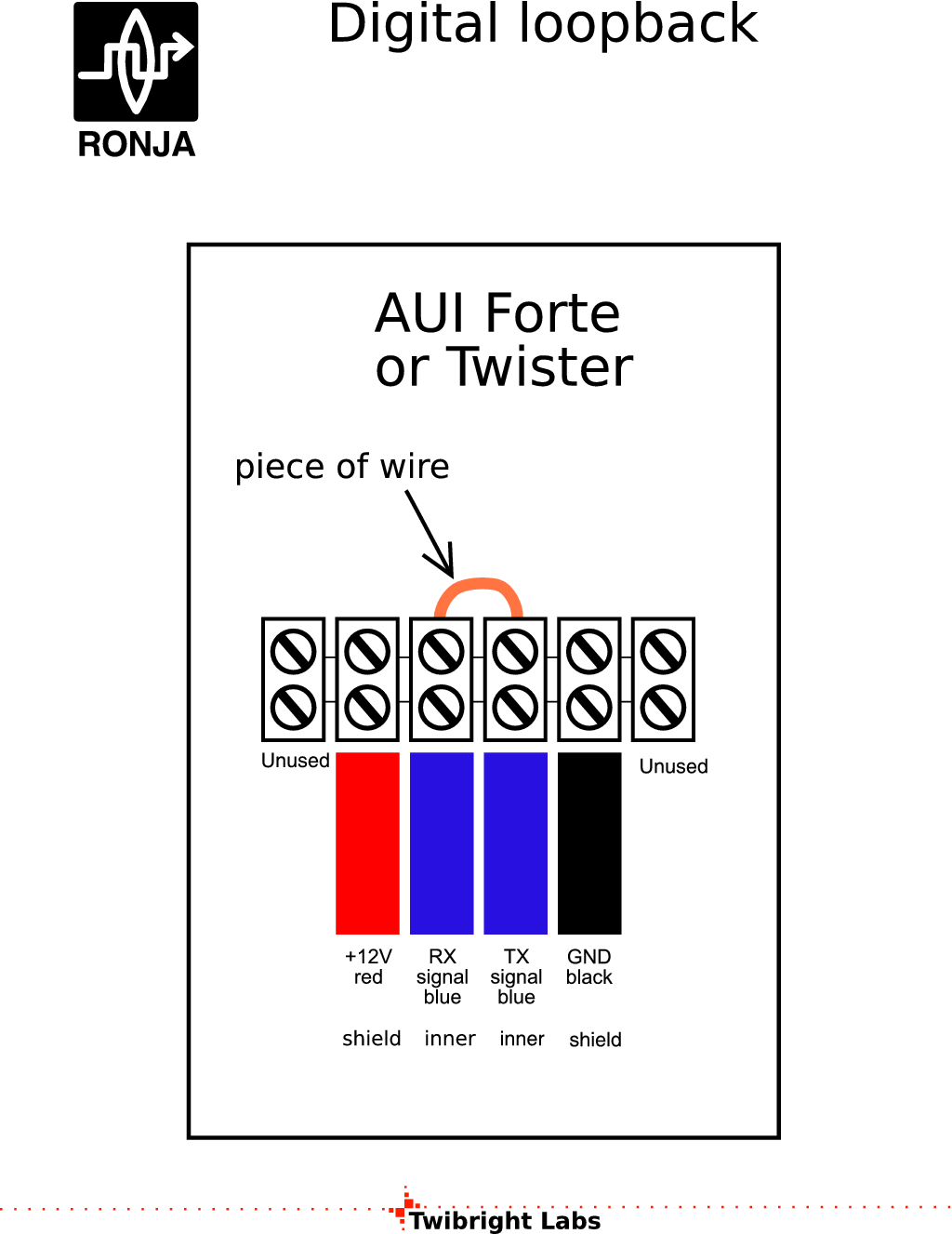