 |
Overview
We are going to build a box with electronics. The box is made of metal and
is closed with a lid. We will install mounting screws pointing outward from it and wires leading from it. Finally we'll solder electronic components inside. |
|
|
|
|
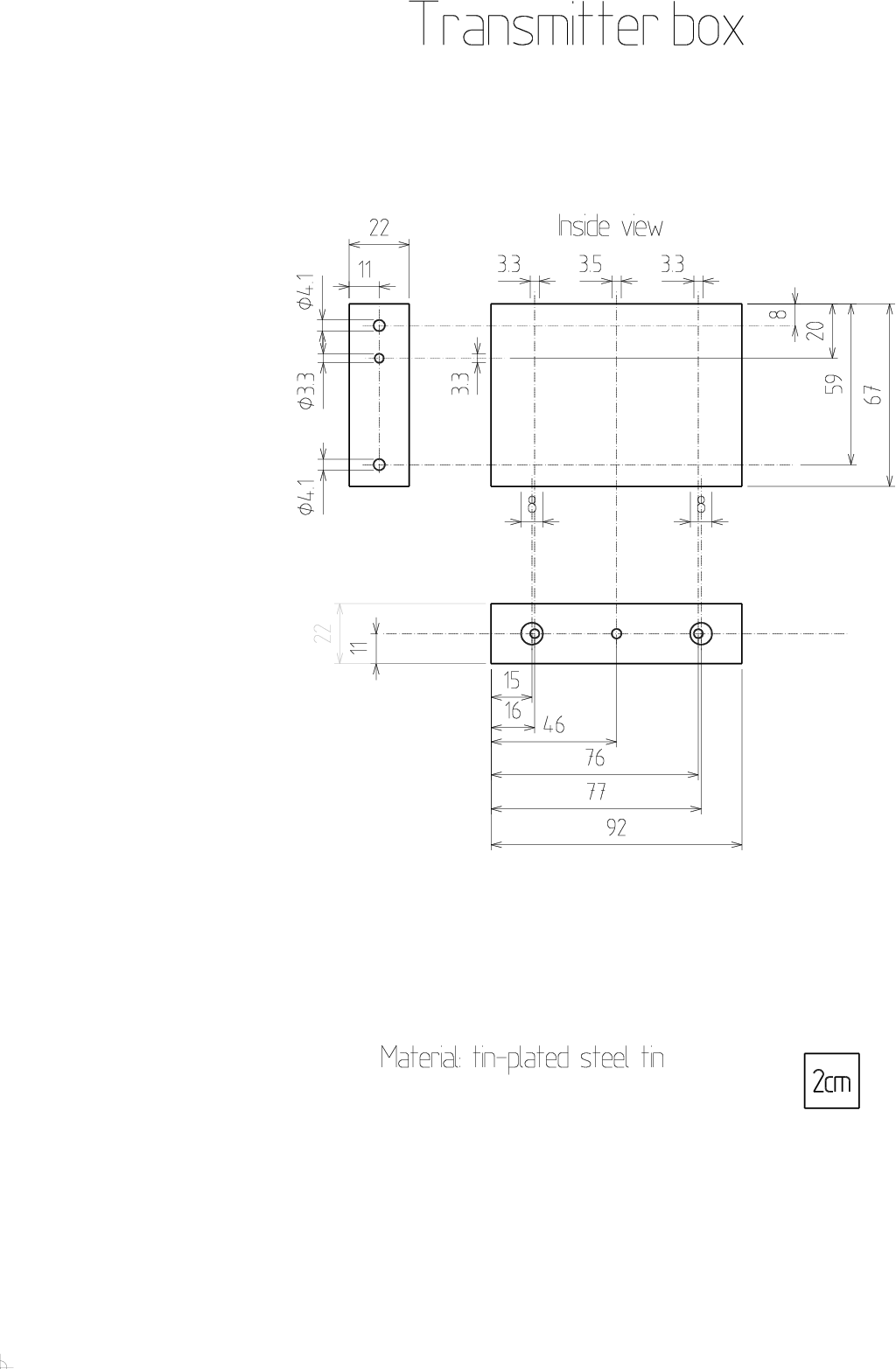
Template
If you have precise printer, use this template to manufacture the
following box. You can also use
RX and TX template together. |
|
|
![Gallery[182]](http://images.twibright.com/tns/lvl2/182.jpg)
|
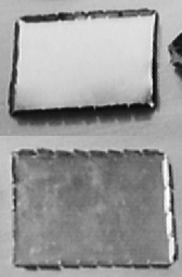
Soldering the bottom If you have factory made
box with 2 lids, solder one lid to the case so that the case has a bottom.
Solder the lid everywhere along the length its edges. (Note: ignore the holes,
I just don't have the right photo without holes.) |
|
|
|
Contact flapsMake contact flaps
on the lid of the case using tin cutters. Adjust their angle using pliers so
that every flap is springed against the case when the lid is closed.
|
|
|
|
|
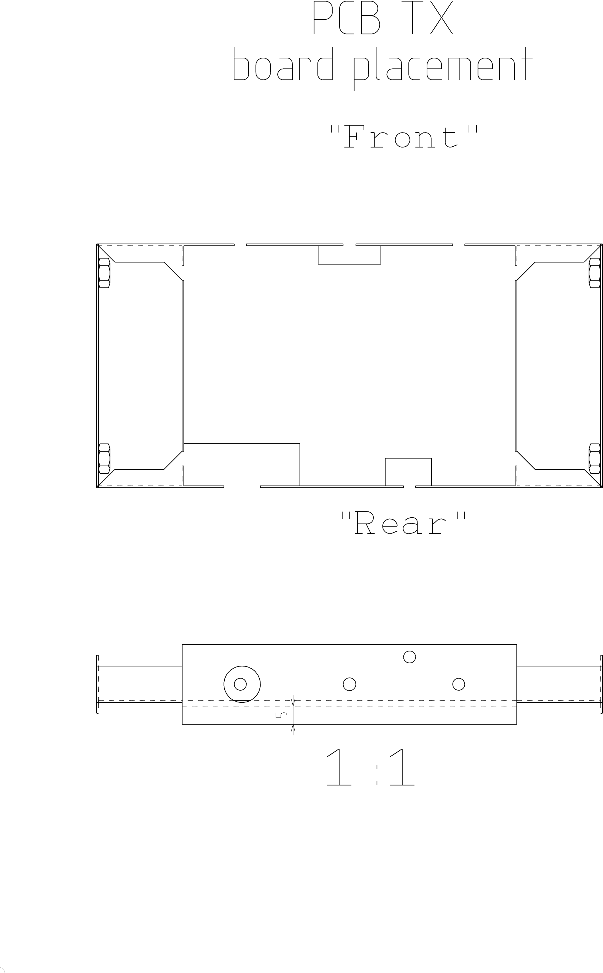
MechanicsDrill out the case
and assemble with 4 M4 bolts and 12 M4 nuts. The bolts are drawn for
130mm optical head. For 90mm they will be shorter. Apply thermal coupling paste on
7805's flange and install 7805 from inner side of the case using M3x6 bolt,
M3 (3.2mm) toothed spring washer and M3 nut. Tighten the M3 nut firmly.
|
|
|
|
-e
|
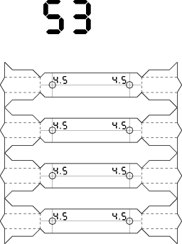
Bracket Template If you plan to
build optical head and the pipe has diameter less than 105mm, skip this box and
the next one. Subtract box width (normally 92mm) from the optical head's pipe
inner diameter. If you don't plan to build optical head, assume 145mm.
Select the template according to the resulting number from the Side template list and print it. The template
is for two boxes, you need just half of it. |
|
|
Make the brackets
- Drill the side template out and bend it. Wash the template off in warm
water.
- Solder the M4 nuts over the holes from the inside.
|
|
|
|
Solder on brackets/nuts
If you have brackets, then solder the brackets to the case, otherwise solder bare
M4 nuts from the outer side over the 4mm holes. |
|
|
|
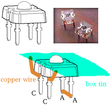
Transmitter LEDPut the HPWT-BD00-F4000 LED
into the 3mm hole in front of transmitter case and solder cathode to the
shielding box tin using two stubs of thick copper wire.
Do not everheat the diode.
These wires, besides of grounding the LED, will conduct heat and thus cool
the LED using the mass of the tin. Connect also the anode
pins together. |
|
|
|
|
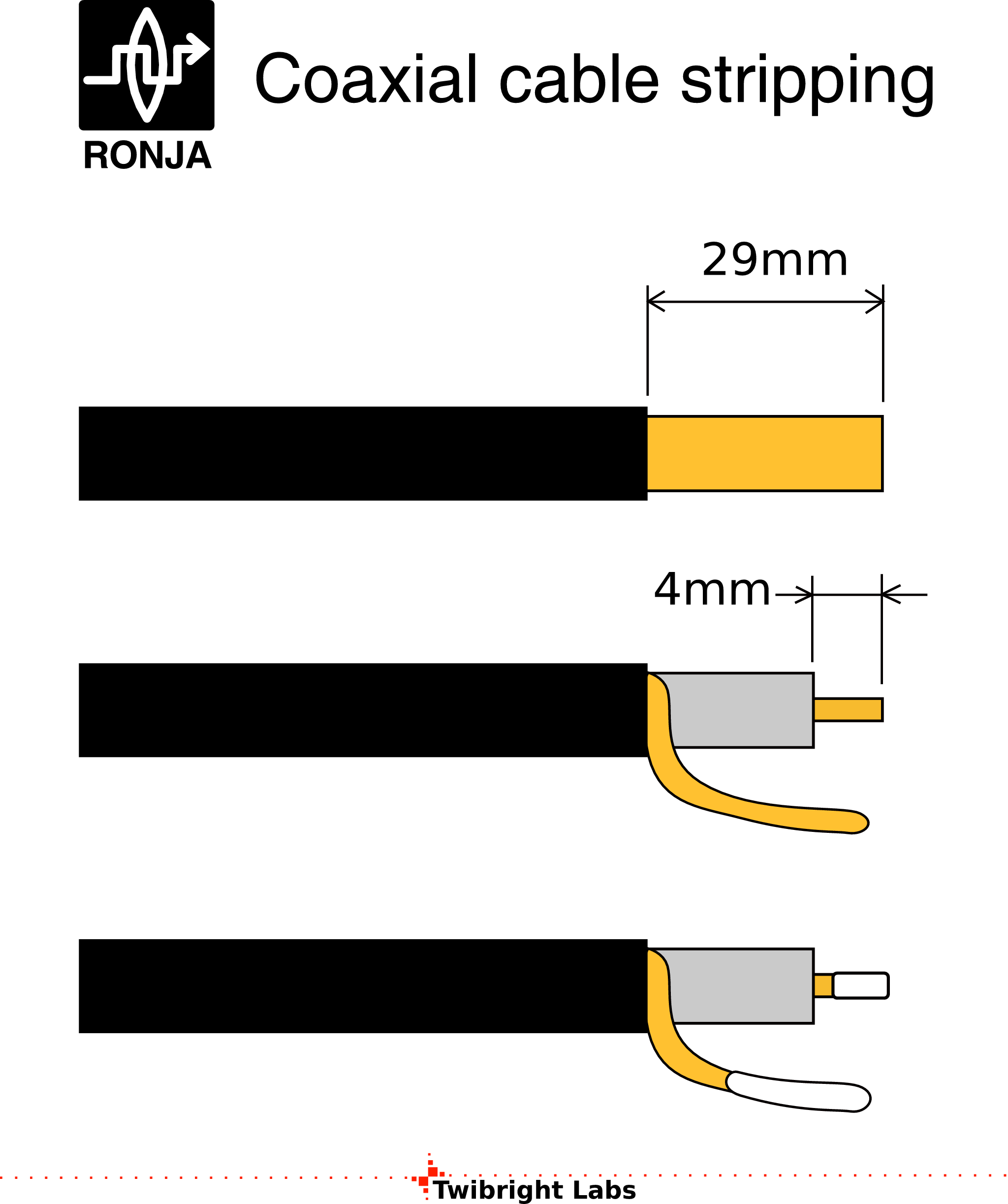
Preparing cables
Cut a 20cm piece of 1.5mm^2 insulated double-conductor cord. Cut a 20cm
piece of shielded single-conductor. Strip all ends of these conductors and
cover them with a solder. |
|
|
|
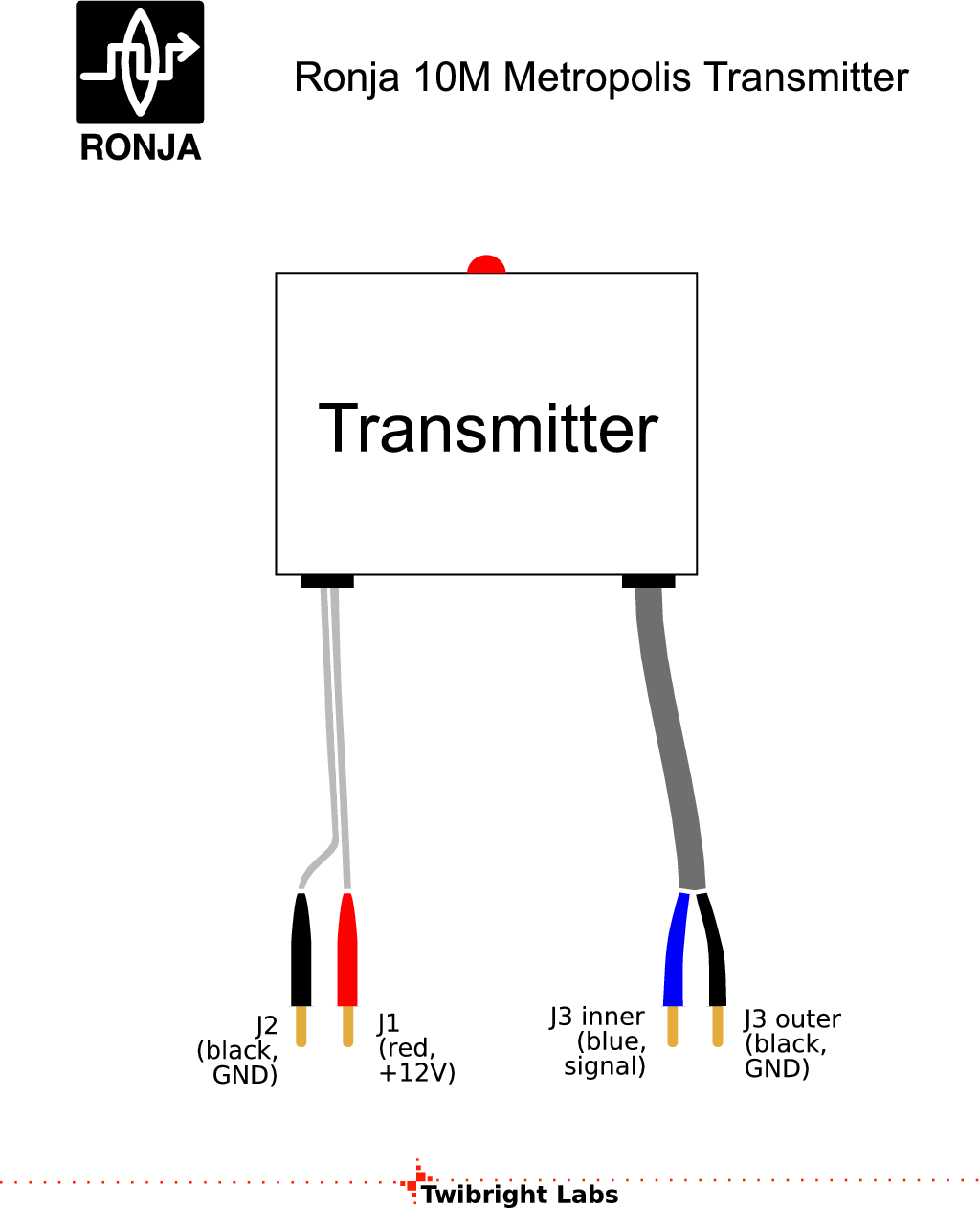
Placing cable leadsPut the cable grommetss in place into
both holes. Put the cables through the grommetss as seen in the picture.
Solder particular ends to the box as seen in the picture. Seal the cables from
both sides of the grommetss with sillicone sealant (you can also use thermal
glue, it faster). |
|
|
|
|
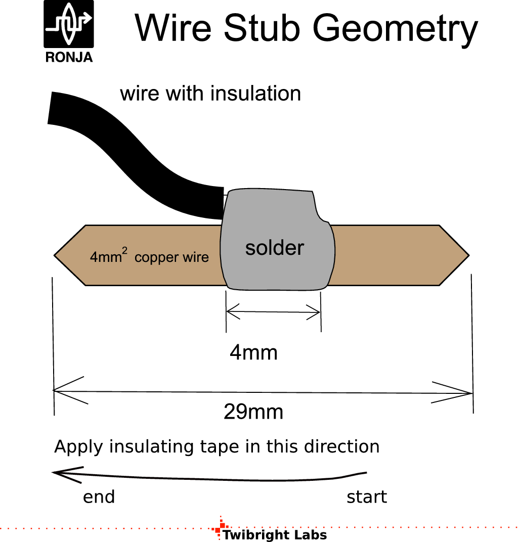
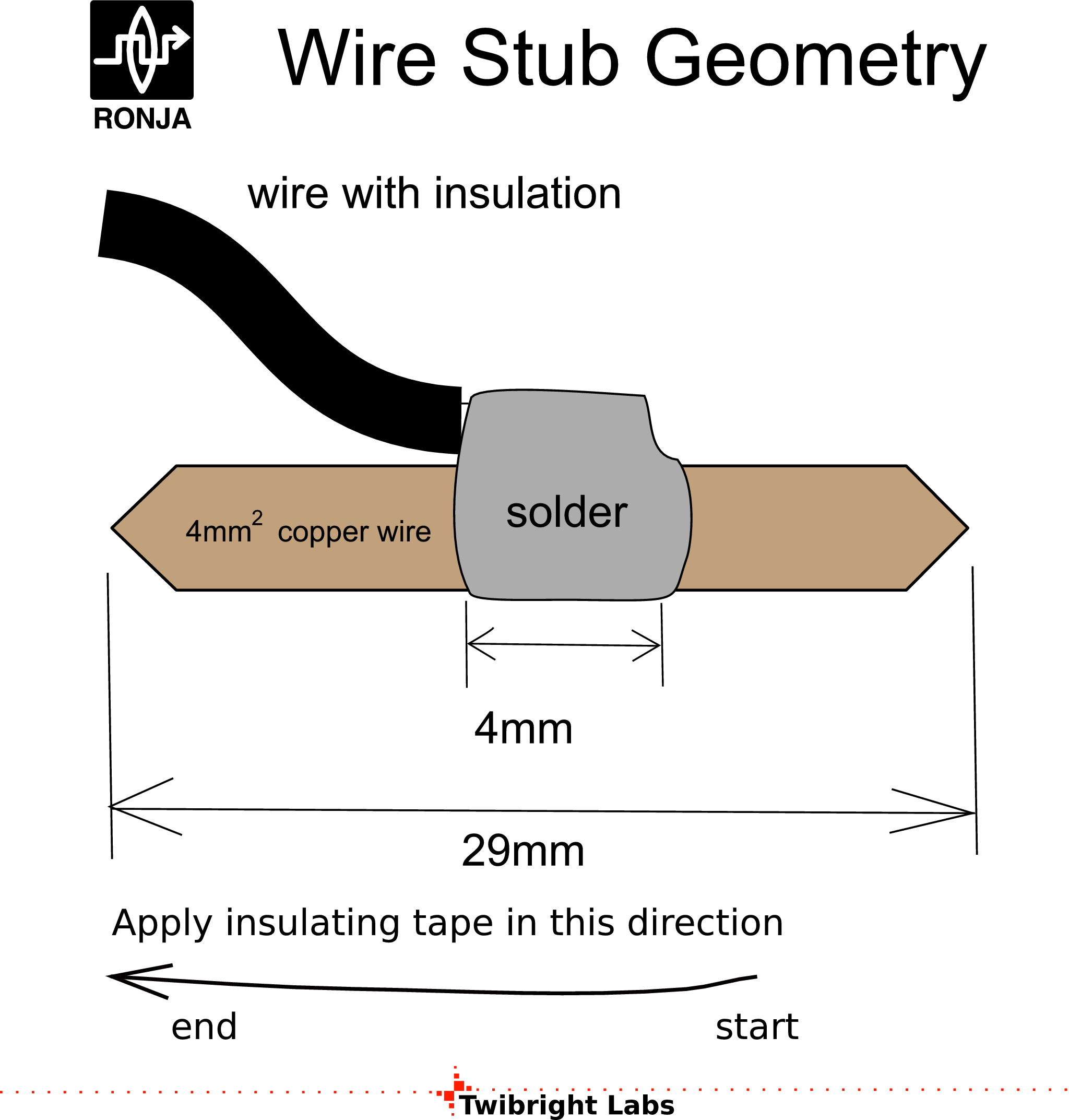
Copper stubs
Solder 4 copper stubs made from 4mm^2 uninsulated hard copper wire on all conductor
on free long ends of cables going from the transmitter according to the drawing. |
|
|
|
|
Colour insulation
Insulate the stubs with colour duct tapes according to the diagram. |
|
|
Making the coil
Take the 8.5mm bit and wind a 10-turn coil on it from the insulated
1mm^2 hard copper wire. |
|
Fucking chips
Solder together the three 74HC04's in stack (like they are fucking),
pin by pin, all pins. |
|
|
|
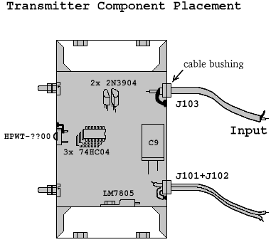
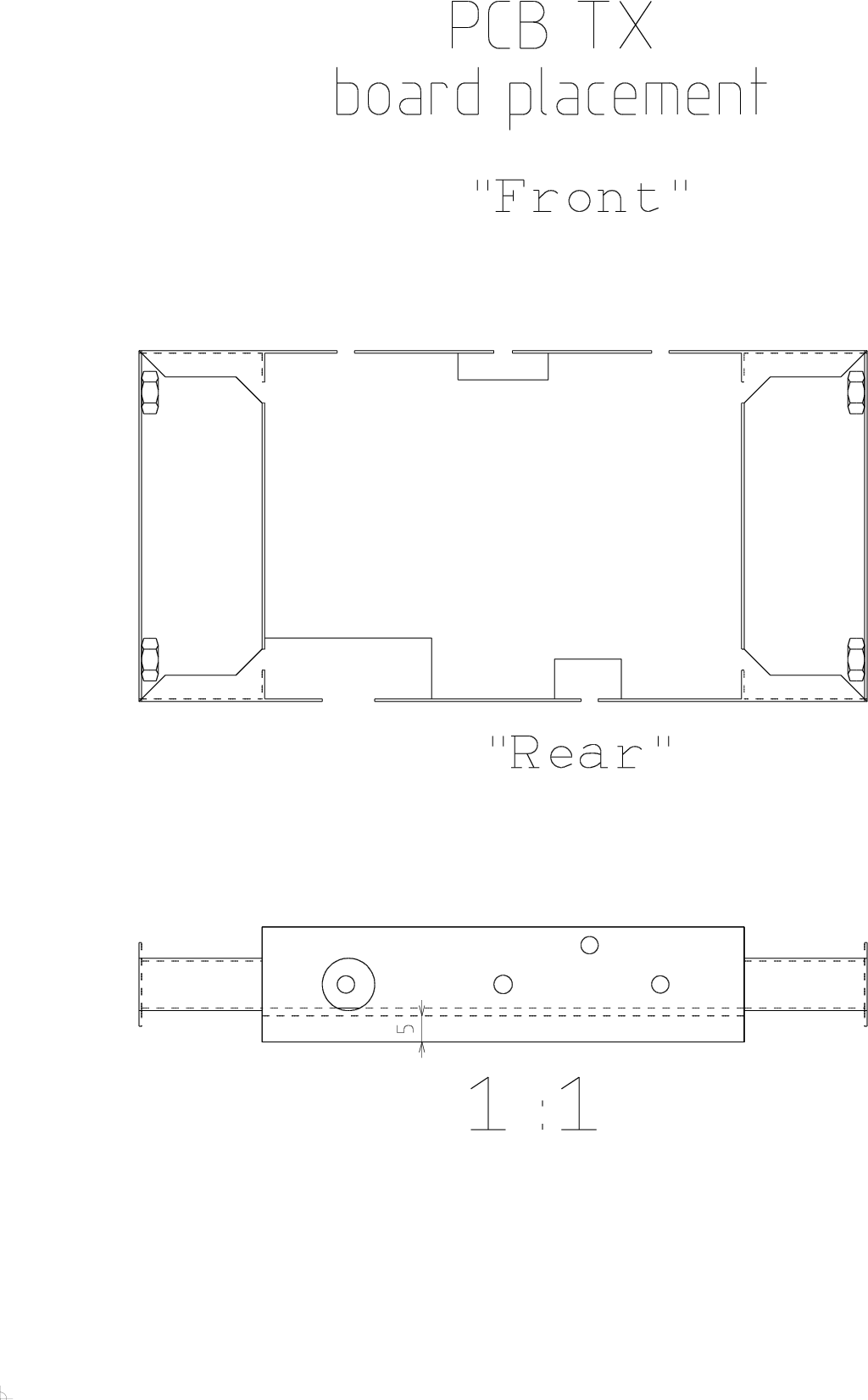
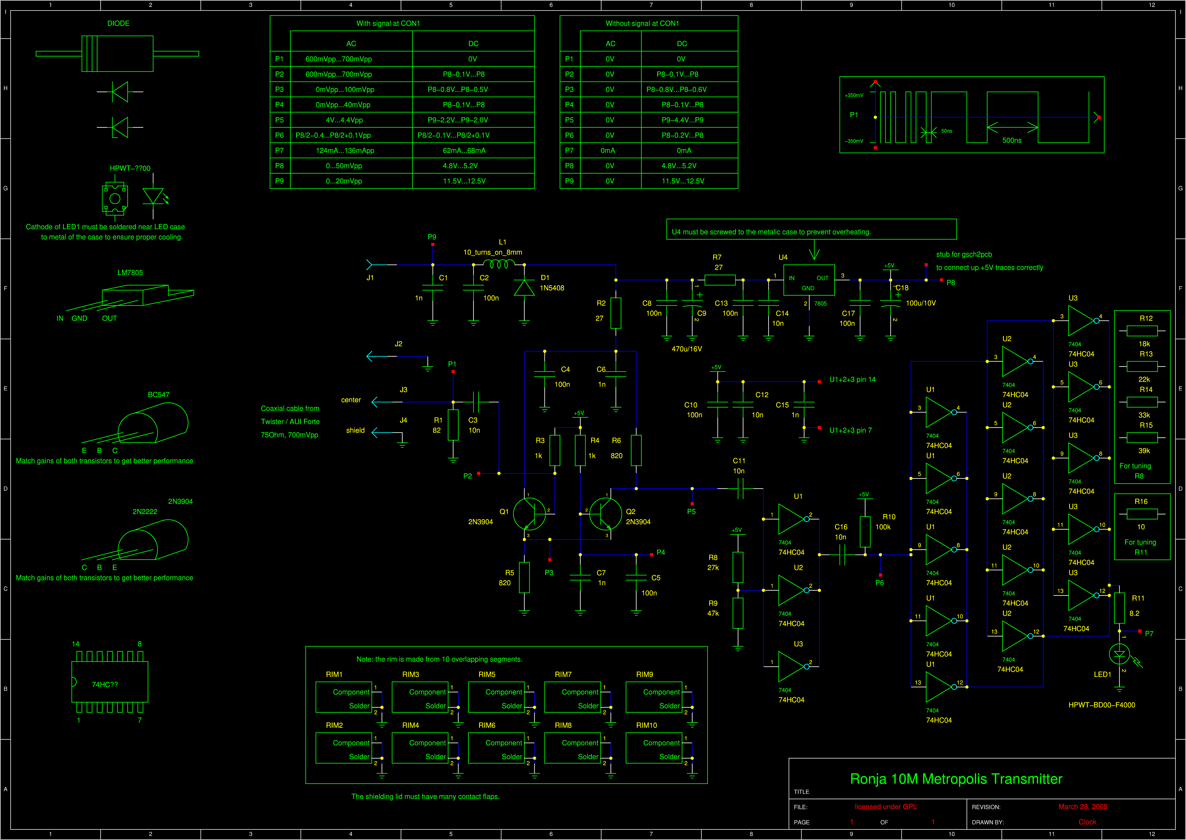
Key components
Place some
key components according to the plan:
- Solder pin 7 (see schematic below for pin 7) of the 3 chips directly
to metal case using a piece of 1mm^2 wire. The connection between pin 7 and
ground should be max. about 5mm long and straight.
- Solder middle pin of (LM)7805 directly to metal case
- Glue down remaining components by hot glue gun
- Print out the schematic and retrace with a pencil every
component and wire you solder in.
|
|
|
|
|
Stereo image
You can take up the notion how the components are going to be packed inside by looking
at stereo photography:
![Gallery[d3a]](http://images.twibright.com/tns/lvl1/d3a.jpg) |
|
|
|
|
There are arrows in the schematic labeled as "P*", where "*" varies. Those are not real components but only virtual measuring points. |
|
|
|
|
Place the components in this sequence:
- U1+2+3 (fucking chips), R1, C1, C2
- C15 (as close to U1+2+3 as possible, directly to ground, short pins) , C12 (right over C15), C10 (right over C12), L1, R11, C16, R9, R10, C3
- D1, C9, C8, R7
- C14 (as close to U4 as possible, short pins, directly to ground), C13 (close to U4), C17 (as close to
U4 as possible, short pins, directly to ground), R2
- C6, C4, R8
- Q1
- R5, R3
- Q2
- C7 (near Q2), C5, R4, R6
- C11
|
|
|
Correctness check
Take the schematic and a multimeter and do a check. Check that the
topology is OK (i. e. the wires lead where they should lead). Measure every
resistor with a multimeter (sometimes it will show less if there is a current
path around). Check every capacitor visually where the value is visible.
Check every diode and transistor junction with diode measuring function of
the multimeter. Scrawl out every part and wire you check on the schematic
with a pencil. |
|
Small schematic
Print out the schematic on a piece of paper size 90x60mm. Overwrite all part
numbers that have been installed different than in schematic. Overwrite all
resistor values that have been chaged during tuning. Write down amplification
factors of both 2N3904 transistors. Glue the paper on the inner side of the
lid. |
|
|
|
Labelling
Print out the Ronja 10M Metropolis Transmitter label.
Fill in and glue on the
outer side of the lid. |
|
|
Washers and nuts
Save 4 M4 washers and 4 M4 nuts for future mounting. |
|

 Contact, support: Clock
on the Internet Relay Chat.© 1998-2016 Karel ‘Clock’ Kulhavý et al..
Contact, support: Clock
on the Internet Relay Chat.© 1998-2016 Karel ‘Clock’ Kulhavý et al.. 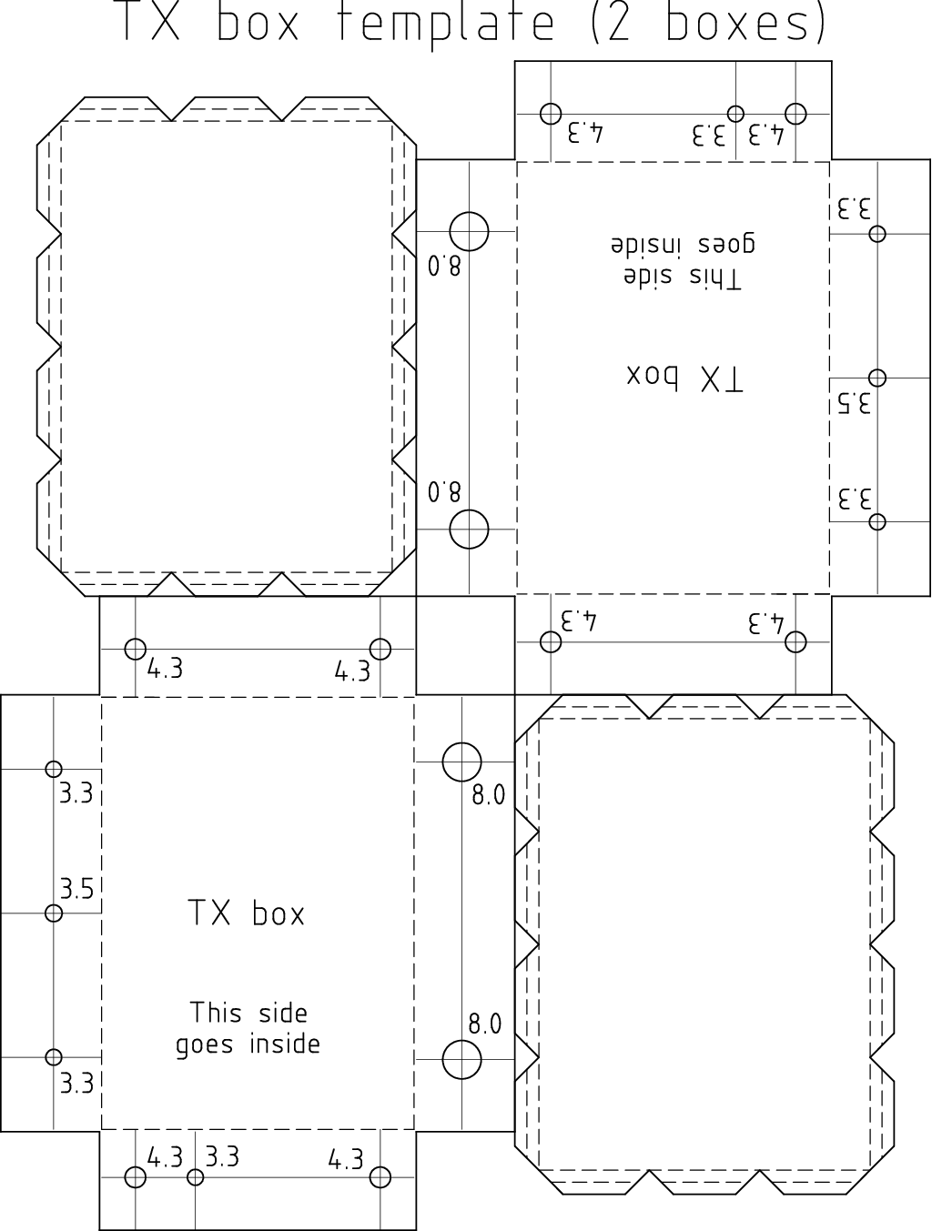
![Gallery[181]](http://images.twibright.com/tns/lvl0/181.jpg)
![Gallery[180]](http://images.twibright.com/tns/lvl0/180.jpg)
![Gallery[182]](http://images.twibright.com/tns/lvl0/182.jpg)

![Gallery[184]](http://images.twibright.com/tns/lvl0/184.jpg)
![Gallery[185]](http://images.twibright.com/tns/lvl0/185.jpg)
![Gallery[186]](http://images.twibright.com/tns/lvl0/186.jpg)
![Gallery[187]](http://images.twibright.com/tns/lvl0/187.jpg)
![Gallery[188]](http://images.twibright.com/tns/lvl0/188.jpg)
![Gallery[189]](http://images.twibright.com/tns/lvl0/189.jpg)
![Gallery[18a]](http://images.twibright.com/tns/lvl0/18a.jpg)
![Gallery[18b]](http://images.twibright.com/tns/lvl0/18b.jpg)
