 |
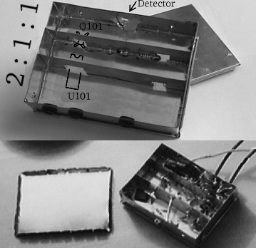
OverviewWe are going to build a tin box with lid here. Box
will be equipped with mounting brackets and wire leads. Finally we'll
solder receiver electronics inside. The result without the lid will look like
this except for mounting brackets: |
|
|
|
|
|
-e
|
Bracket Template If you plan to
build optical head and the pipe has diameter less than 105mm, skip this box and
the next one. Subtract box width (normally 92mm) from the optical head's pipe
inner diameter. If you don't plan to build optical head, assume 145mm.
Select the template according to the resulting number from the Side template list and print it. The template
is for two boxes, you need just half of it. |
|
|
Make the brackets
- Drill the side template out and bend it. Wash the template off in warm
water.
- Solder the M4 nuts over the holes from the inside.
|
|
|
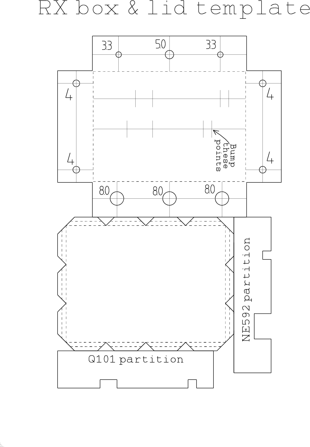
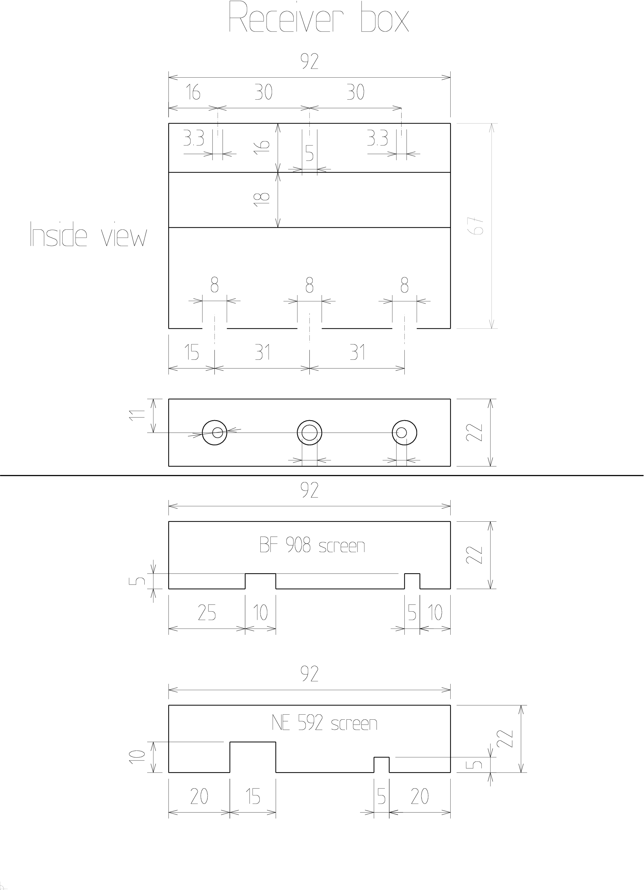
Main box
Note the picture shows an older type of the box.
- Glue the box template on tinned steel plate.
- Cut and drill out.
- Bump the indicated points.
- Bend into a box shape.
- Remove the template with warm water
- Solder the corners up
- Solder the partitions (strips with square notches)
inside the box. The strip positions are given by the bumps on the bottom.
Solder all along
their gap, not just in several points.
![Gallery[167]](http://images.twibright.com/tns/lvl1/167.jpg) |
|
|
Solder on brackets/nuts
If you have brackets, then solder the brackets to the case, otherwise solder bare
M4 nuts from the outer side over the 4mm holes. |
|
|
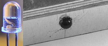
DetectorPut the BPW43 or SFH203 detector into the 5mm hole in the
case and solder anode to the
box. The Anode (A, the longer pin) is described in the lower left
corner of the schematic (below). When inserting the detector into the hole, make
sure the detector is perpendicular to the plane (is not askew) and about 1/3 of
the plastic body is protruding out. The chip must be inside otherwise catches
intereference! After soldering, fix it from the inner side using the
thermal glue gun (optional, recommended). |
|
|
![Gallery[164]](http://images.twibright.com/tns/lvl2/164.jpg)
|
Grommet
Put the cable grommets into the 8mm holes. Note: the box in the picture should
have mounting brackets soldered on. |
|
|
Cutting cables
Cut the following types and lengths of cables:
| Qty | Type | Length
| | 3 | shielded single-conductor | 20cm
| |
|
|
|
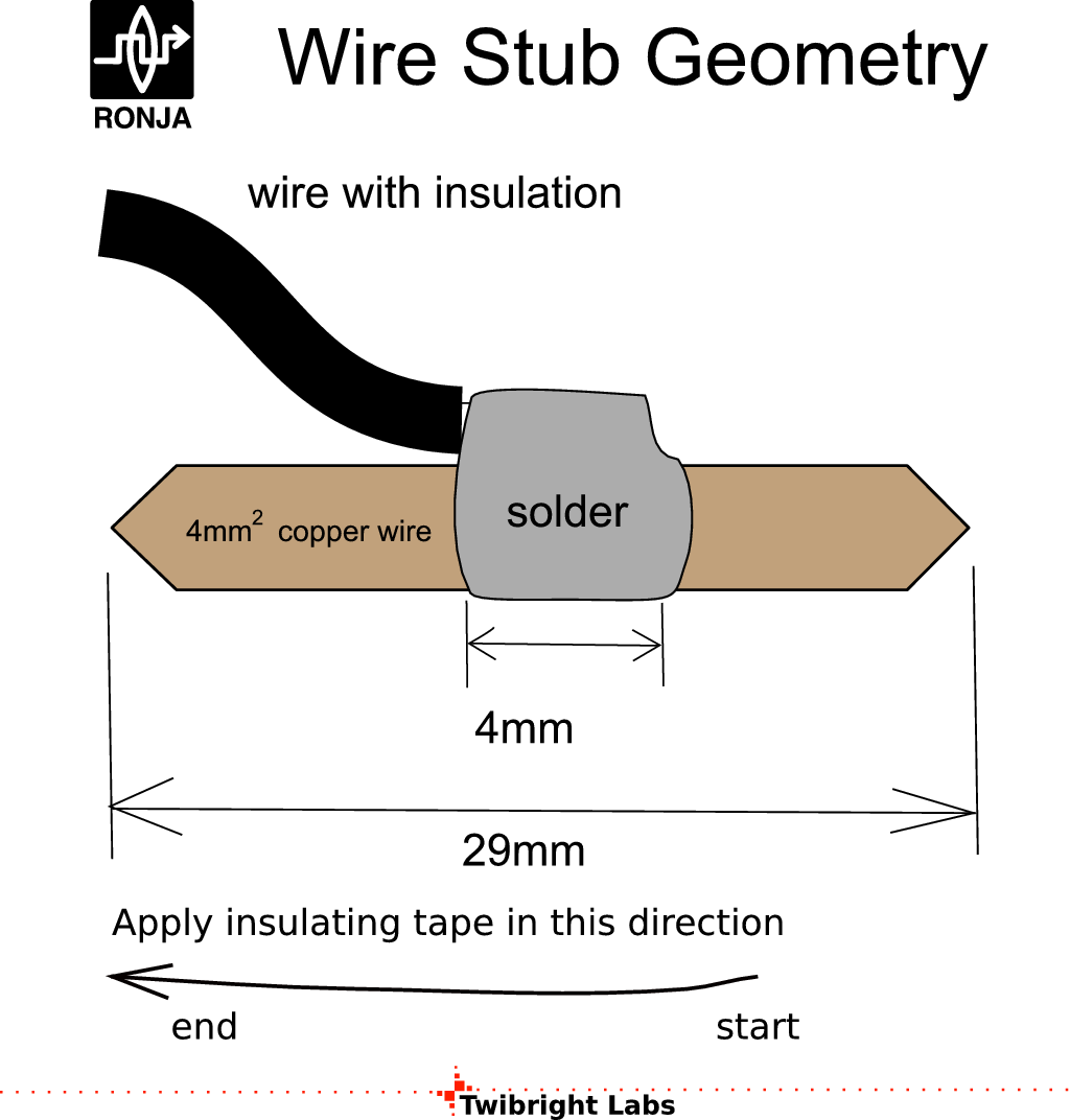
Stripping
Strip 29mm
of the outer insulation from the shielded cable on both sides. Strip 4mm of the
inner insulation from the shielded cable on both sides.
Cover all bare ends with solder. |
|
|
|
|
Installing
cable leads Put the bare ends through the grommets as seen in the picture.
Leave the middle cable's shield unconnected but solder the remaining shields to
the box. Seal the cables inside the grommets with sillicone sealant (you can
also use thermal glue, it is faster). Seal from both inside and outside of the
grommets. When sealing the outside take care not to occupy the place where the
lid will be (the rim of the box). |
|
|
|
|
Copper stubs
The cables ends that are not inserted into the box need copper stubs.
Solder 6 stubs made from 4mm^2 uninsulated solid copper wire. |
|
|
|
|
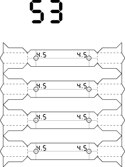
Colour insulation
Insulate the stubs with colour duct tapes according to the diagram. |
|
|
Making the coilTake the 8.5mm bit bit and wind a 10-turn coil on it from the
insulated1mm^2 hard copper wire. |
|
|
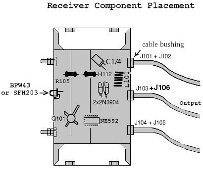
Key componentsPlace some important components into the box according to the drawing. Fix them
by soldering on their ground lead. If they don't have any ground lead and you mind them rolling all around inside the box, you
can glue them down using thermal glue gun. |
|
|
|
|
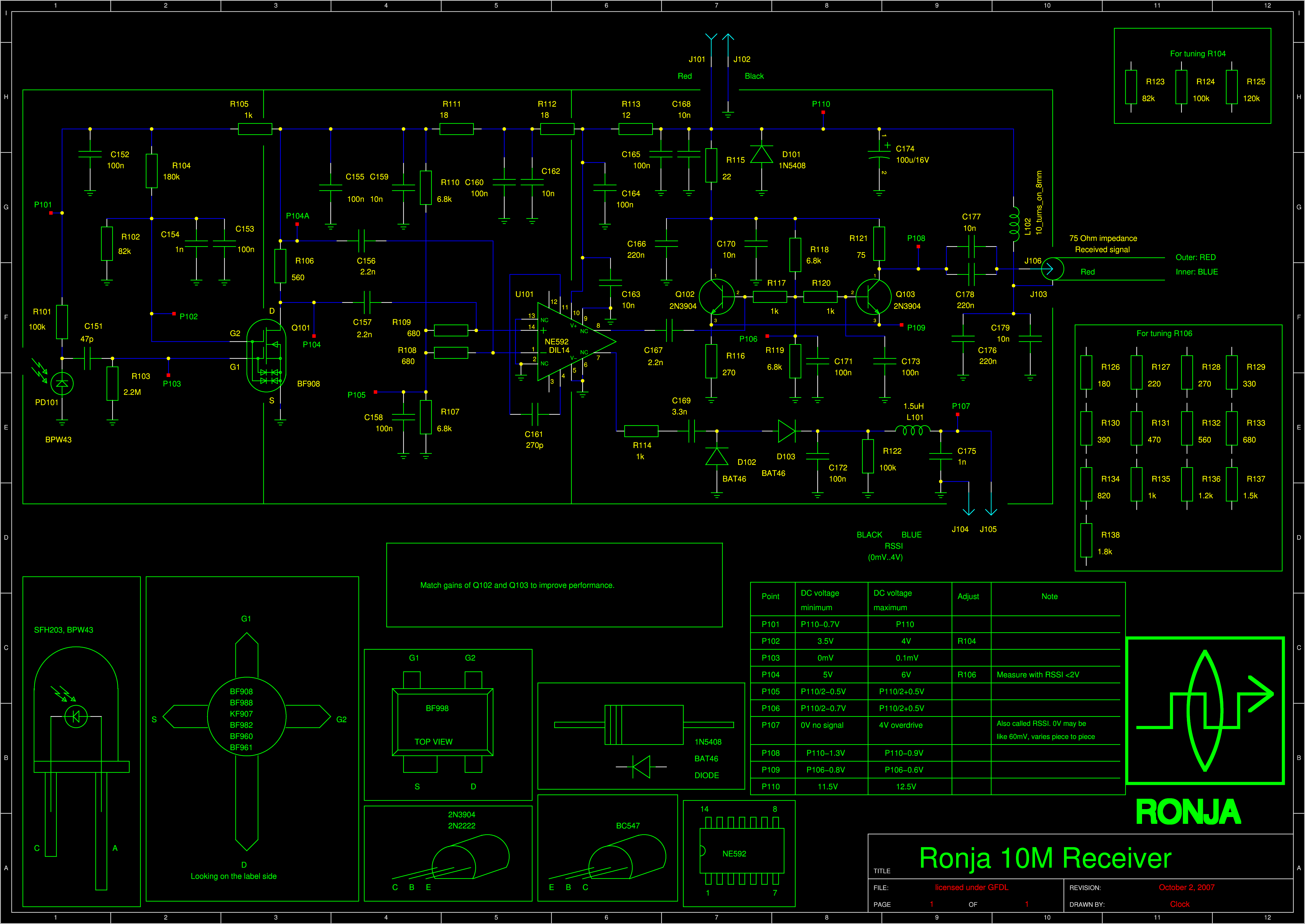
We are going to place components according to a schematic. There are arrows in the schematic labeled "P*" where "*" varies. They don't mean any component, they are just test points. |
|
|
|
|
Stereo pictureYou can view a stereo picture of populated RX to get a notion how
the components are mounted inside prior to starting soldering them down. Please
note there should be mounting brackets instead of the screws:
![Gallery[d39]](http://images.twibright.com/tns/lvl1/d39.jpg) |
|
|
|
|
Now the following components are already installed in the
box:
|
|
|
|
|
Place the remaining components
according to the schematic in this sequence:
- C168 close to J101
- C165 close to J101
- C178 close to J103
- C179 close to J103
- C163 close to U101
- C164 close to U101
- C154 close to Q101
- C153 close to Q101
- L102
- R101
- C173
- C167
- D101
- R103
- C152
- C161
- C155
- C151
- C177
- C175
- L101
- R122
- C172
- D103
- C162
- C157
- D102
|
- R102
- R104
- C156
- R111
- R113
- R108
- R109
- R110
- R115
- C158
- C166
- R117
- R120
- R119
- R107
- C169
- R116
- R121
- C178
- R114
- R118
- C160
- C170
- C159
- C171
|
|
|
|
Correctness check
Take the schematic and a multimeter and check everything except
R106 (still missing). Check that the
topology is OK (i. e. the wires lead where they should lead). Measure every
resistor with a multimeter (sometimes it will show less if there is a current
path around). Check every capacitor visually where the value is visible.
Check every diode and transistor junction with diode measuring function of
the multimeter. Scrawl out every part and wire you check on the schematic
with a pencil. Check visually all soldered joints for quality and resolder
all joints where suspicion may arise. |
|
R106
Connect 12V regulated supply: + to J101 (red) and - to J102 (black).
Set multimeter to 200mA and put red probe to P104A and black probe to
P104. Measure current.
Disconnect from power. Select R106 according to this table:
| Current [mA] | R106 [Ohm]
|
|---|
| 3-3.6 | 1.8k |
| 3.6-4.4 | 1.5k |
| 4.4-5.5 | 1.2k |
| 5.5-6.5 | 1k |
| 6.5-8 | 820 |
| 8-10 | 680 |
| 10-12 | 560 |
| 12-14 | 470 |
| 14-17 | 390 |
| 17-20 | 330 |
| 20-24 | 270 |
| 24-30 | 220 |
| 30-36 | 180 |
Solder the R106 into the receiver. |
|
Schematic inside the lid
Print the small schematic (see above). Overwrite all part numbers that have been installed different than in schematic. Overwrite all resistor values that have been changed during tuning. Write down amplification factors of both 2N3904 transistors. Glue the paper on the inner side of the lid. |
|
|
|
Label
Print out the Ronja 10M Receiver label. Fill in the label and stick on the
outer side of the lid. |
|
|
Washers and nuts
Save the 4 M4 washers and 4 M4 nuts for future mounting. |
|

 Contact, support: Clock
on the Internet Relay Chat.© 1998-2016 Karel ‘Clock’ Kulhavý et al..
Contact, support: Clock
on the Internet Relay Chat.© 1998-2016 Karel ‘Clock’ Kulhavý et al.. ![Gallery[59b]](http://images.twibright.com/tns/lvl1/59b.jpg)
![Gallery[16b]](http://images.twibright.com/tns/lvl1/16b.jpg)
![Gallery[684]](http://images.twibright.com/tns/lvl1/684.jpg)

![Gallery[16a]](http://images.twibright.com/tns/lvl1/16a.jpg)


![Gallery[16b]](http://images.twibright.com/tns/lvl0/16b.jpg)
![Gallery[16c]](http://images.twibright.com/tns/lvl0/16c.jpg)
![Gallery[16d]](http://images.twibright.com/tns/lvl0/16d.jpg)
![Gallery[16e]](http://images.twibright.com/tns/lvl0/16e.jpg)
![Gallery[16f]](http://images.twibright.com/tns/lvl0/16f.jpg)
![Gallery[170]](http://images.twibright.com/tns/lvl0/170.jpg)
![Gallery[173]](http://images.twibright.com/tns/lvl0/173.jpg)
