 |
Description
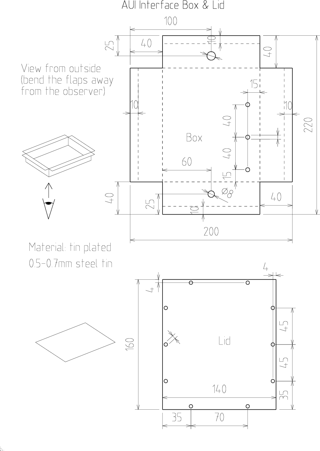
The electronics is placed in a metal box. The body is made of
tin-plated steel tin of thickness about 0.5mm.
The lid is from tin-plated steel
tin, or aluminium or copper tin. They are connected with 10 M4x6 galvanized
bolts with hex head and 10 M4 galvanized nuts. |
|
|
|
|
BoxCut out the body and lid shape
from tin, drill the holes. Form the tin into depicted shape. Use the 20x20x3 steel L-sections fastened in vice for bending.
Solder the tin together
in corners. Place the lid over the body and drill through with 4.3mm bit,
securing the already drilled holes against movement by inserting M4 bolts. |
|
|
Grommets, wire nutInsert the grommets.
- Place the wire nut near the 8mm grommet (10.5mm hole).
- Drill with
3.3mm bit through all five holes of the nut.
Use inserted M3 bolts to keep the nut in position during drilling.
- And attach with 5 M3x15 bolts,5 M3 washers, and
5 M3 nuts.
Place bolt heads inside the box. Tighten firmly.
- Note: the pictures are of old prototype with only 4 wire nut terminals
instead of correct 6.
|
|
|
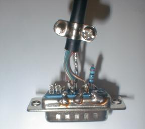
AUI CableCut a 1
meter long piece of shielded 4-conductor cable. Solder the AUI connector (CANON
15-pin male) on one end of the cable together with a 39R resistor (see
the schematic, the closed box in the upper right corner. |
|
|
|
|
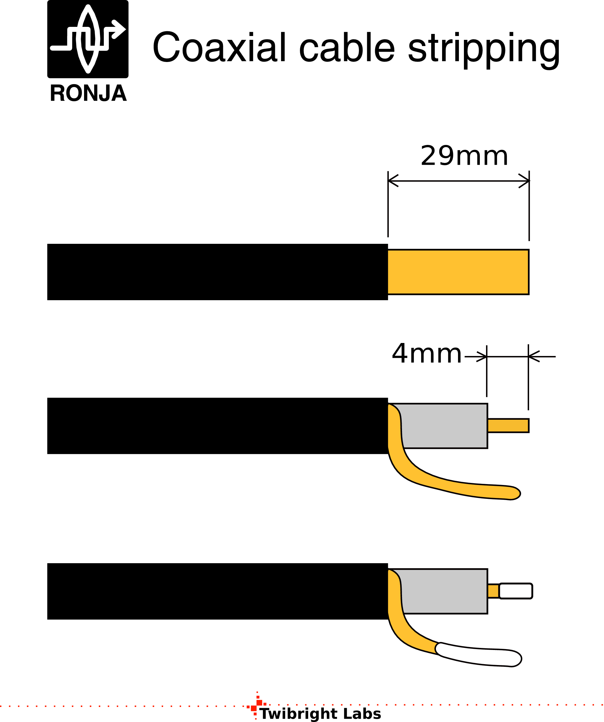
Cutting cables
Cut two 10cm
long pieces of shielded single-conductor cable. Strip all ends of the cables
and cover them with solder. |
|
|
|
|
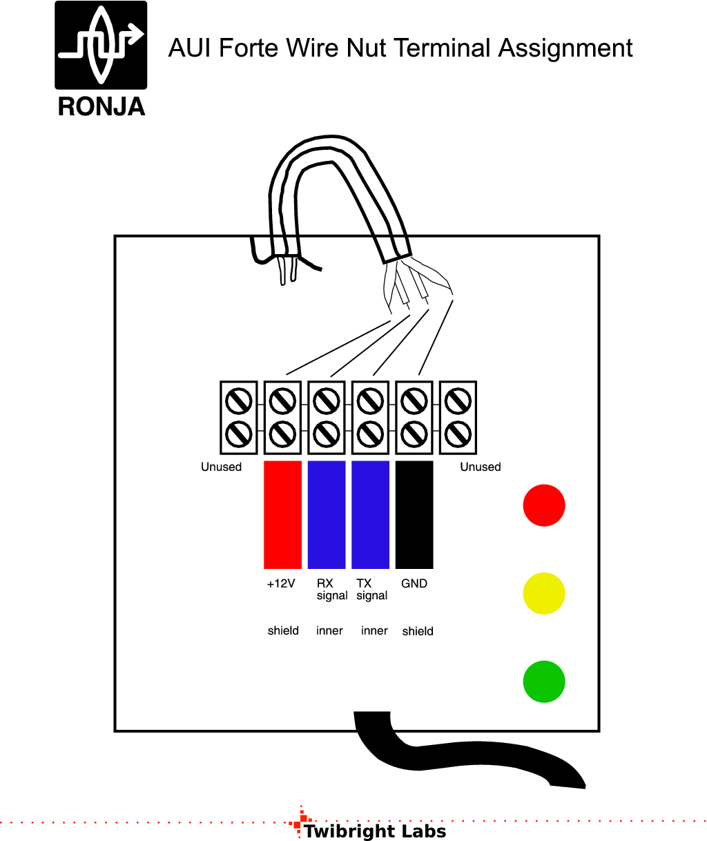
RX/TX Cables Install the three
cables into the AUI box and solder one shield to the ground according to the
drawing. |
|
|
|
|
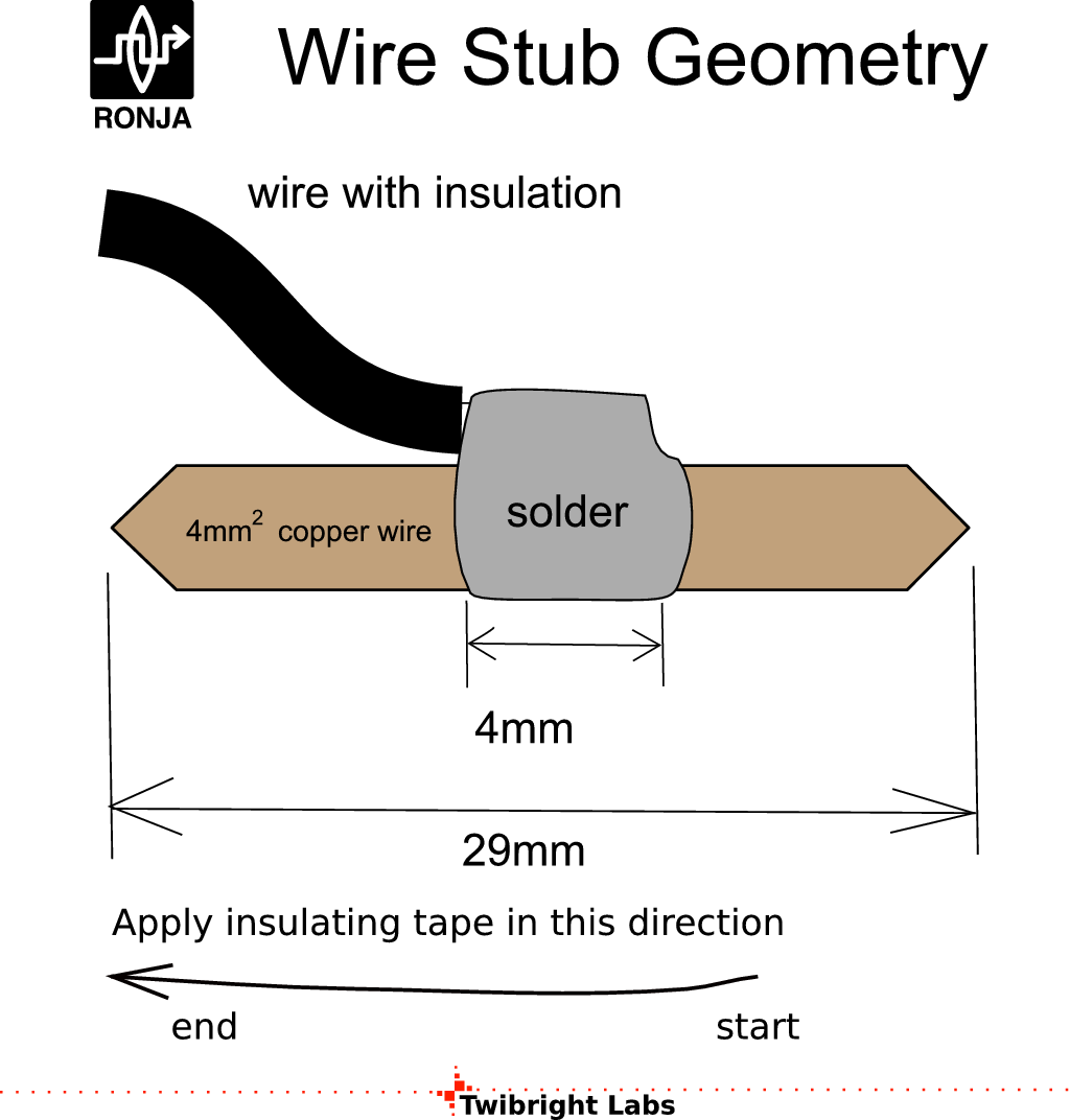
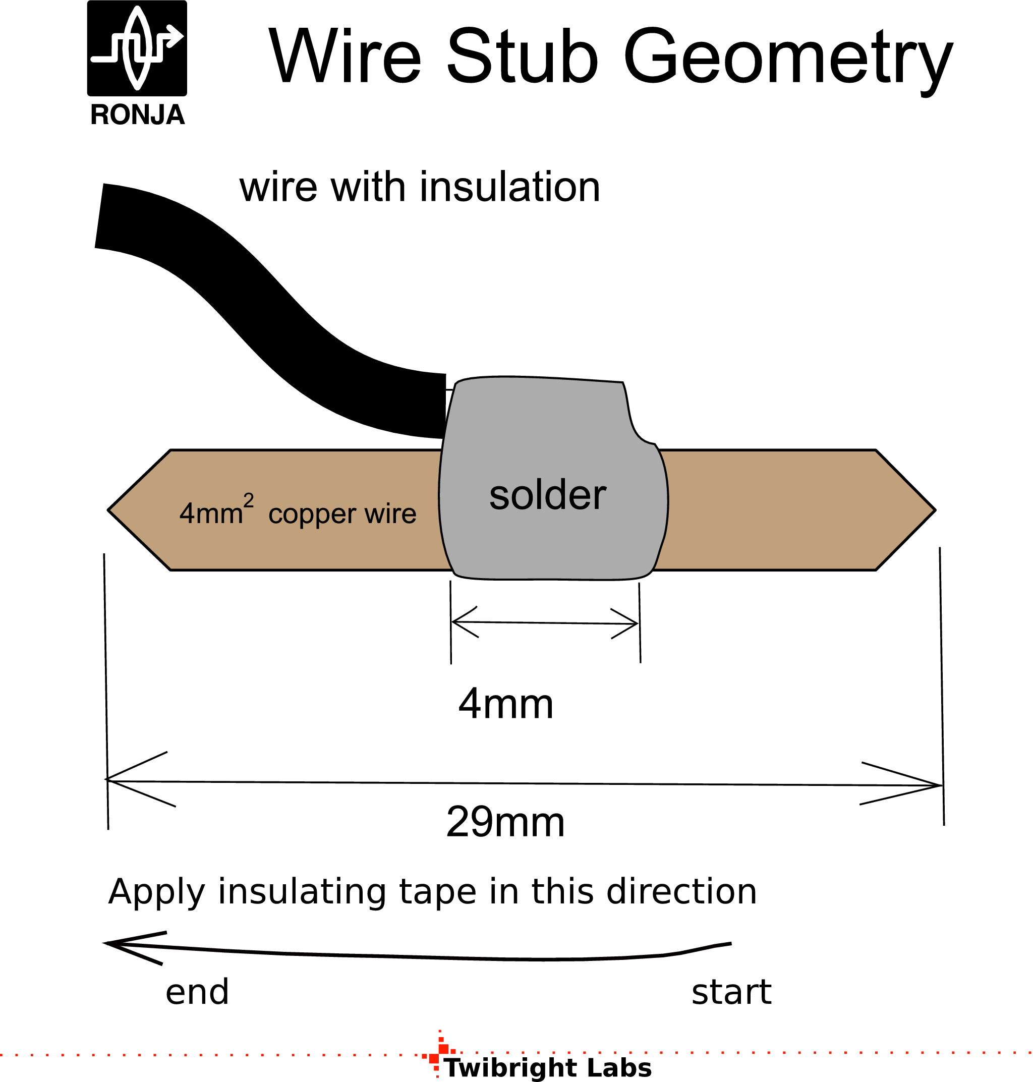
Stubs
Solder four 4mm^2 hard wires (uninsulated) on the remaining
ends of the cable. |
|
|
|
|
Insulation
- Stick coloured strips of insulating tape on the box as on the drawing
- Insulate wire ends with corresponding colour and plug into the wire nut
and tighten down.
|
|
|
|
|
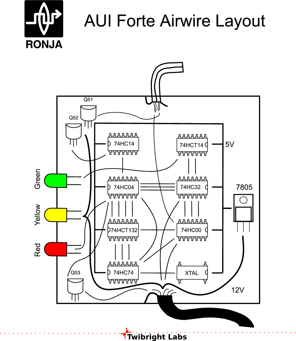
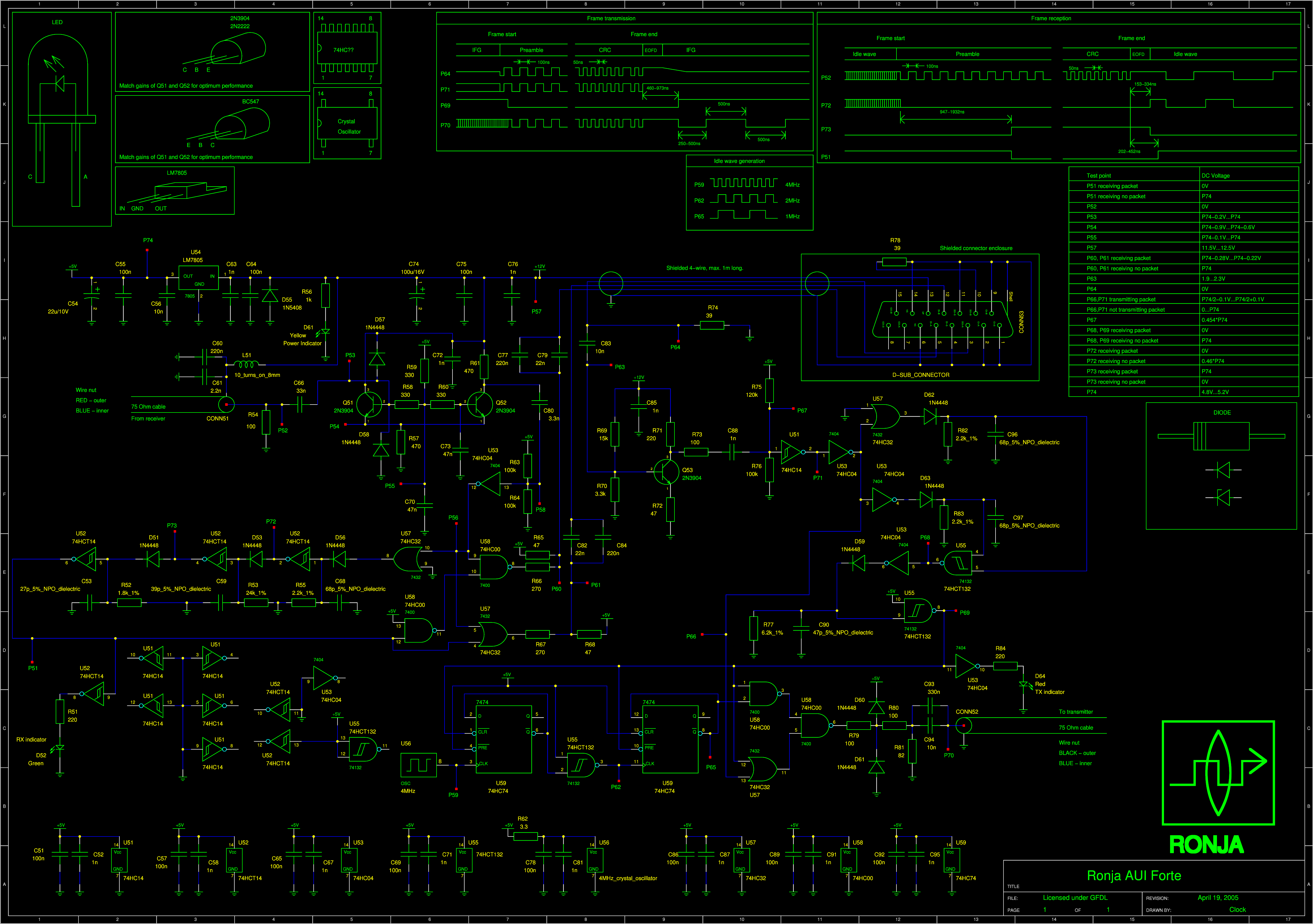
Populating with components
- Semiconductor components
will be installed according to the placement plan.
- Semiconductors will be wired together using wires, resistors, capcitors,
diodes etc.
|
|
|
|
|
There are arrows labeled "P*" where "*" varies.
Those are not real components, just measurement points. |
|
|
|
|
Placing components
Place
components according to the plan. Before placing each integrated circuit,
carve the part number (for example 74HCT132) on the bottom side using
sharp metal stylus or stick a sticker and write it on. Write a refdes
(e. g. U51) beside the IC on the tin using fine-tip permanent waterproof marker.
Some of the following example
photos have pins pointing towards the tin. Recommended way is to make
pins point away from the tin. |
|
|
|
|
SolderingWire up the remainder of the circuit in this priority:
- Remaining components
- Remaining wires
|
|
|
Correctness checkTake the schematic and a multimeter and do
a check. Check that the topology is OK (i. e. the wires lead where they should
lead). Check every resistor - either read the value, decode the strip code or measure the resistor with a multimeter (sometimes it will show less if
there is a current path around). Check every capacitor visually where the value
is visible. Check every diode and transistor junction with diode measuring
function of the multimeter. Scrawl out every part and wire you check on the
schematic with a pencil. |
|
|
|
Labeling
Print out the "small print" schematic (see Soldering above) on a laser printer. Overwrite
part numbers where different parts or equivalents were used.
Glue the paper on the inner side of
the lid.
Print out the Ronja AUI Forte label. Fill in the label and glue the label
on the outer side of the lid. |
|
|

 Contact, support: Clock
on the Internet Relay Chat.© 1998-2016 Karel ‘Clock’ Kulhavý et al..
Contact, support: Clock
on the Internet Relay Chat.© 1998-2016 Karel ‘Clock’ Kulhavý et al.. ![Gallery[156]](http://images.twibright.com/tns/lvl1/156.jpg)
![Gallery[587]](http://images.twibright.com/tns/lvl1/587.jpg)
![Gallery[152]](http://images.twibright.com/tns/lvl1/152.jpg)
![Gallery[153]](http://images.twibright.com/tns/lvl1/153.jpg)
![Gallery[14b]](http://images.twibright.com/tns/lvl1/14b.jpg)
![Gallery[148]](http://images.twibright.com/tns/lvl1/148.jpg)
![Gallery[d4f]](http://images.twibright.com/tns/lvl1/d4f.jpg)
![Gallery[149]](http://images.twibright.com/tns/lvl1/149.jpg)
![Gallery[147]](http://images.twibright.com/tns/lvl1/147.jpg)
![Gallery[14a]](http://images.twibright.com/tns/lvl1/14a.jpg)

![Gallery[137]](http://images.twibright.com/tns/lvl1/137.jpg)
![Gallery[138]](http://images.twibright.com/tns/lvl1/138.jpg)
![Gallery[139]](http://images.twibright.com/tns/lvl0/139.jpg)
![Gallery[13a]](http://images.twibright.com/tns/lvl0/13a.jpg)
![Gallery[13b]](http://images.twibright.com/tns/lvl0/13b.jpg)
![Gallery[13c]](http://images.twibright.com/tns/lvl0/13c.jpg)
![Gallery[13d]](http://images.twibright.com/tns/lvl0/13d.jpg)
![Gallery[13e]](http://images.twibright.com/tns/lvl0/13e.jpg)
![Gallery[13f]](http://images.twibright.com/tns/lvl0/13f.jpg)
![Gallery[140]](http://images.twibright.com/tns/lvl0/140.jpg)
![Gallery[141]](http://images.twibright.com/tns/lvl0/141.jpg)
![Gallery[142]](http://images.twibright.com/tns/lvl0/142.jpg)
![Gallery[143]](http://images.twibright.com/tns/lvl0/143.jpg)
![Gallery[14f]](http://images.twibright.com/tns/lvl0/14f.jpg)
![Gallery[14e]](http://images.twibright.com/tns/lvl0/14e.jpg)
![Gallery[6e7]](http://images.twibright.com/tns/lvl0/6e7.jpg)
![Gallery[6e8]](http://images.twibright.com/tns/lvl0/6e8.jpg)
![Gallery[6e9]](http://images.twibright.com/tns/lvl0/6e9.jpg)
![Gallery[6ea]](http://images.twibright.com/tns/lvl0/6ea.jpg)
![Gallery[6eb]](http://images.twibright.com/tns/lvl0/6eb.jpg)
![Gallery[6ec]](http://images.twibright.com/tns/lvl0/6ec.jpg)
![Gallery[6ed]](http://images.twibright.com/tns/lvl0/6ed.jpg)
![Gallery[6ee]](http://images.twibright.com/tns/lvl0/6ee.jpg)
![Gallery[6ef]](http://images.twibright.com/tns/lvl0/6ef.jpg)
![Gallery[6f0]](http://images.twibright.com/tns/lvl0/6f0.jpg)
![Gallery[6f1]](http://images.twibright.com/tns/lvl0/6f1.jpg)
![Gallery[6f2]](http://images.twibright.com/tns/lvl0/6f2.jpg)
![Gallery[6f3]](http://images.twibright.com/tns/lvl0/6f3.jpg)
![Gallery[6f4]](http://images.twibright.com/tns/lvl0/6f4.jpg)
![Gallery[6f5]](http://images.twibright.com/tns/lvl0/6f5.jpg)
![Gallery[6f6]](http://images.twibright.com/tns/lvl0/6f6.jpg)
![Gallery[6f7]](http://images.twibright.com/tns/lvl0/6f7.jpg)
![Gallery[6f8]](http://images.twibright.com/tns/lvl0/6f8.jpg)
![Gallery[6f9]](http://images.twibright.com/tns/lvl0/6f9.jpg)
![Gallery[6fa]](http://images.twibright.com/tns/lvl0/6fa.jpg)
![Gallery[6fb]](http://images.twibright.com/tns/lvl0/6fb.jpg)
![Gallery[6fc]](http://images.twibright.com/tns/lvl0/6fc.jpg)
![Gallery[6fd]](http://images.twibright.com/tns/lvl0/6fd.jpg)
![Gallery[6fe]](http://images.twibright.com/tns/lvl0/6fe.jpg)
![Gallery[6ff]](http://images.twibright.com/tns/lvl0/6ff.jpg)
