This is a page common for all modules that describes important fundamentals in making various part for Ronja. Read this page at least once before you do anything in real.
Some of the operations produce excessive noise that may be unhealthy, especially from immediate proximity:
If the noise is unpleasant, feel free to plug your ears with cotton or paper napkins to be sure no hearing damage occurs.
Dimensions are sometimes specified in the guide with tolerances. For example 15+15-0 mm means typical 15 mm, maximum 30 mm and minimum 15 mm. 500+10-5mm means minimum 495mm, typical 500mm and maximum 510mm.
|
Sometimes templates are provided which speed up the machining tremendously. Your printer has to be accurate for this. Print out this calibration drawing and ensure accuracy. |
For cutting metal, a cutting emulsion is recommended. It prevents the cuting edge(s) from overheating and thermally damaging the tool and also reduces friction. You can make a suitable emulsion by mixing water : vegetable oil in ratio 4 : 1 and adding soap and mixing well until it becomes homogeneous. If you can't make emulsion, use vegetable oil instead. Do not use plain water as it will corrode the cutting edge and render it useless.
Vegetable oil is better than mineral oil because doesn't damage your skin and also makes more pleasant stench when gets overheated.
Apply the emulsion/oil with an old paintbrush or a syringe.
Apply cooling emulsion during the cutting as needed or at least oil (preferrably vegetable).
After cutting, remove burrs using a file (or massive sharp screwdriver if you do not have suitable file).
Take care not to cut off your finger. The cutters are dangerous.
Unless you want to have scars like a warrior, treat the edges of the sheet with respect. Sometimes there are razor blades, sometimes needles.
First measure the exact position of the centre with a ruler and/or sliding measure (and a square if you have got a square). Use a sharp centre punch to mark the points and lines and hammer out a small hole in the future centre with the centre punch and a hammer.
Do not wear gloves when drilling. The drill could catch the glove and tear your finger off. Do not hold the piece by bare hand but use pliers or clamp.
If the hole diameter is bigger than 5mm, use some smaller bit (4mm or smaller) to predrill the hole and then drill it out with the intended diameter. Use of a drill stand is recommended for all drilling. Predrill with 2mm bit where precision is critical. Best option is a ready-made drillstand. Those are very rigid and drilling is very easy with them because they don't vibrate at all.
Apply the cutting emulsion before drilling on the bit and on the material. If the emulsion evaporates, add more during drilling.
After drilling, cut down the hole's edges using a reamer drill, bigger drill bit in the drill, or bigger drill bit in hand. Or you can use a file or big screwdriver.
If you drill a tin, put a block of wood under it if possible. After drilling a tin, it is possible to remove burrs by banging them down flat with a hammer on an anvil or vice and repeating drilling if some of them got inside the hole. If you can't get block of wood, drill with very slow feed at the end to prevent exit burr.
If you drill tin as is, the tin will get deformed at the end, the bit will catch it and tear the hole apart. Even worse, sometimes the tin gets wound up on the bit. There is a risk that you will get cut with sharp tin edge during this accident.
To prevent the risk, take two pieces of thin wooden board and first drill the required diameter into the top board. Then clamp the tin between the boards using grippers. Position the intended hole center exactly in the middle of the wooden hole and tighten. Now drill through. The problem will go away.
If the soldering iron's tip becomes dirty, heat it up and wipe it into a piece of rag or wet sponge so that it becomes clean again. If you omit this you will not be able to make a reliable joint.
![Gallery[d40]](http://images.twibright.com/tns/lvl1/d40.jpg) |
![Gallery[d41]](http://images.twibright.com/tns/lvl1/d41.jpg) |
![Gallery[d42]](http://images.twibright.com/tns/lvl1/d42.jpg) |
If the surface of the molten solder becomes wrinkled and the solder refuses to flow apart, then there's a layer of oxide. Apply a drop of molten colophonium into the joint and make sure you don't use temperature higher than one necessary to reliably melt the solder. High temperature promotes oxide formation.
Do not spare resin flux and do not waste the solder. Put there only as much tin as necessary for the joint to be firm, but do not make balls from solder. Before soldering parts together, cover them with tin using solder and resin flux (be sure the tin adheres evenly to the part). Then put them together and add some tin, resin flux, and leave the soldering iron on until all the tin becomes liquid, then remove the soldering iron and don't move the joint until it thoroughyl solidifies. The surface of the tin must be clean and shiny.
![Gallery[d3e]](http://images.twibright.com/tns/lvl1/d3e.jpg) |
![Gallery[d3f]](http://images.twibright.com/tns/lvl1/d3f.jpg) |
-- examples of OK and wrong joint.
The components in an airwire electronic construction must not touch each other. If the thin insulation lacquer got accidentally corrupted, the device would be unreliable then. Short circuit between the touching components would occur randomly.
If bending the wires or cutting them near the soldered joint, reheat the joint after. Mechanical stress on the wire causes the joint to crack and to become a cold joint. Remelting the cold joint again and letting it cool down correctly makes it a good joint again.
When letting the soldered joints cool down, do not move the wires. Also don't blow at the joint to make it cool down quicker. Both things result in cold joint.
Use methylated spirit (denatured ethanol) or isopropanol and a rag or a paper. Wipe the soldered tin-plate before soldering with the fluid and dry. This will remove remains of fat, soluble lacquer and glue and make soldering easier.
Q101 in the receiver is sensitive to static electricity and switching surges.
Do not overheat the semiconductors. If you can't get tin on the pin and would need too long time, relax and wait until the part cools and then continue. Or hold the pin with pliers between the end and the part, so that the pliers will suck off the heat spreading over the pin.
Use a soldering iron with grounded tip. If you use those gun-style irons with a loop of thick wire, connect an aligator-clip to the loop and connect it reliably electrically with the metal box. Also don't turn on or off the switch of soldering gun when touching the Q101 or something near it in the circuit. This is somewhat tricky, because normally one uses constant switching on and off of the gun to regulate the tip temperature.
Capacitors usually have the value printed on them. The most widespread system works like this: There is for example "104". You interpret is as 10 and 4. 10 is mantissa and 4 exponent, the unit is picofarad. So that 10*10^4pF=100nF. The capacitor's value is 100nF. Some multimeters can even measure capacitors.
Electrolytic capacitors must be polarized right. They have usually a minus (-) marker strip printed on one side. The lead that is near this marker is (-). Former Czech TESLA capacitors had the + wire marked by a groove around one edge and the - was connected with the body.
Resistors have got a colour strip code on them. Decode it according to the following chart:
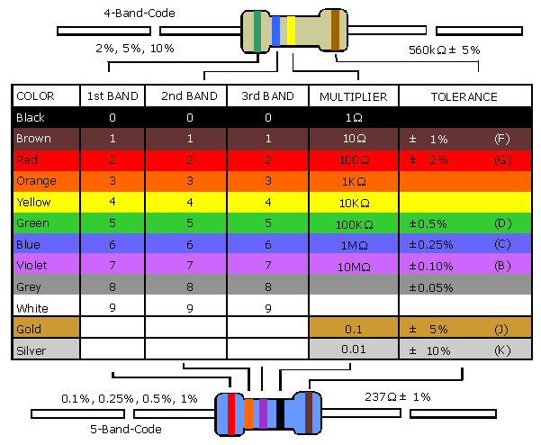
… or take a multimeter and measure the value.
Diode pinouts are in the schematic. Zener diodes (those with a hook from cathode in their symbol) and plain silicon diodes have usually a remarkable strip on one side, which signs always the cathode. Diode is -|<|-, cathode is the -| and anode the <|-. You can check them with a multimeter - the red lead is on anode when the selector is on diode measurement and the multimeter display shows the voltage drop across the diode at 1mA current.
Transistor and IC pinouts are in the schematic.
You can use a part that has just some suffix added to the type required in the guide, unless it's explicitly forbidden. For example, 74HC32 is required and you can use 74HC32B. Or DS26LS32 is required and you can use DS26LS32CN or DS26LS32N.
Cut the pins as short as conveniently possible. But make them long enough for the soldered joint not to touch the part's case because that makes the parts unreliable by overheating. Route the wires also in possibly short routes. Do not leave neighbouring parts like resistors and capacitors in touch, because sometimes the lacquer gets corrupted and a contact may occur.
When sealing a seam, first put small amount of the sealant on both sides of the seam. Spread it and knead it firmly with your fingers to coat the surrunding surfaces of the seam reliably. Then apply the big amount of sealant and shape it with your fingers. Then wipe your fingers into a dry rag (or piece of paper) completely. Do not try to wash the sealant off your fingers with soap and water as it is impossible.
After the sealant dries, seal the seam once more. Often the sealant breaks during hardening and omitting this would cause a failure of the device after a month or so when enough water accumulates inside the pipe coming through the hole.

 Contact, support: Clock
on the Internet Relay Chat.© 1998-2016 Karel ‘Clock’ Kulhavý et al..
Contact, support: Clock
on the Internet Relay Chat.© 1998-2016 Karel ‘Clock’ Kulhavý et al.. 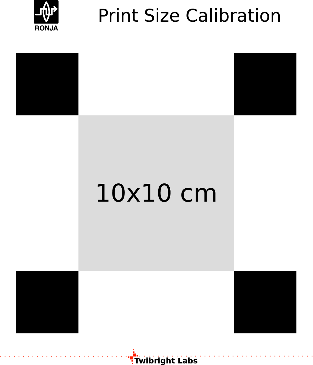