|
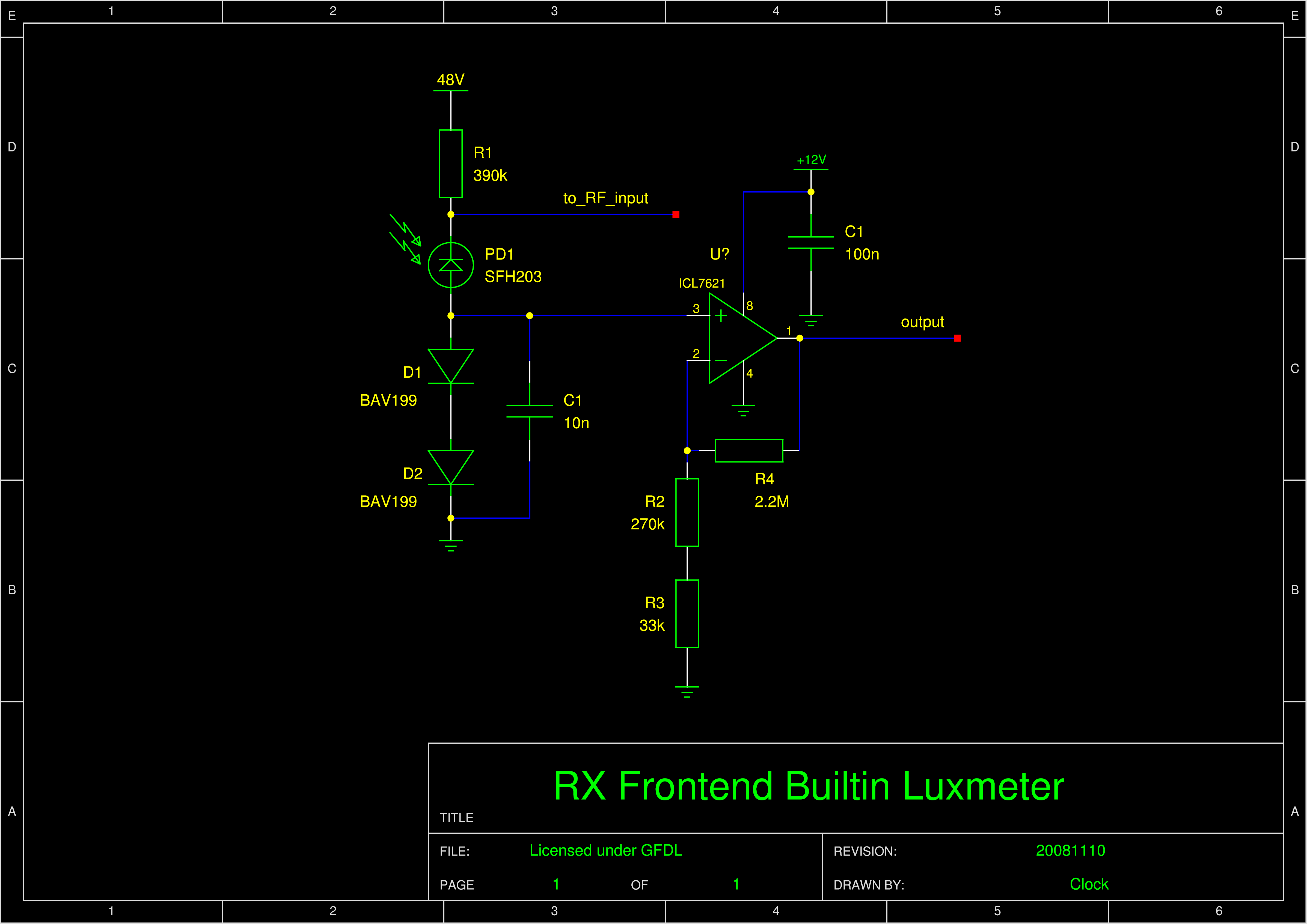
CA3140 was chosen for his high inout impedance (FET), ability to output close to the lower rail, and it's availability. Two diodes were chosen because BAV199 comes as two diodes together and also to get more signal to overcome the opamp offset. The BAV199 has the emission coefficient n=1.0246 and 1N4148 1.906 (NXP SPICE models). The higher resistor will be 2.2M. To get 1V per 10dB, the lower must be 2.2M/(1/(ln(10)*vt*2*n)-1). vt=25.85mV. That's 305.6k for BAV199 and 645.6k for 1N4148. That's 270k and 33k for BAV199 and 560k and 82k for 1N4148. Originally there was a 100n capacitor but for low readings the output was slow. I replaced with 10n and calculated only a negligible amount of shot noise escapes the 10n capacitor and gets into the RF input through the PIN diode capacitance. | |||||||||||||||||||||||||||||||||||||
The calibration is based on these measured values:
| 40uA | 3.97V |
| 400uA | 4.95V |
The corresponding equation is then current=exp((voltage-8.28V)*2.3496). The 8.28V constant is when the current reaches 1A (theoretically if the diode hadn't any ersistance). PDF, PS

 Contact, support: Clock
on the Internet Relay Chat.© 1998-2016 Karel ‘Clock’ Kulhavý et al..
Contact, support: Clock
on the Internet Relay Chat.© 1998-2016 Karel ‘Clock’ Kulhavý et al..