Since the largest power consumption is in the first stages - up to estimated 80mA in worst conditions - simple resistor/capacitor filters are not an option because they would not filter adequately or have a too large voltage drop.
We have 5 active stages, we need 5 LRC filters. The filter should filter from 50 kHz to 10GHz. Parasitic components must be taken into account: coil capacitym, capacitor inductance and resistor capacity. Adequate damping has to be provided and the filter simulated as a whole because the individual stages will influence.
For easy prototyping the parasitics will be calculated on TMD. Changing to SMD later will just improve the filter performance.
Let's permit a total voltage drop of 0.5V that's 0.1V per stage. Let's assume 100mA current draw from the first stage and nothing from the rest for simplicity. That gives 1 Ohm per stage. We have to divide this to allow for damping resistor (the resistance of the coil is not guaranteed) that gives 0.5 Ohm. For the manufacturer Fastron at Distrelec this gives 6.8uH, for Epcos 47uH, another Fastron 2.2uH, another Epcos 3.3uH, another Epcos 10uH, another Fastron 220uH, another Fastron 47uH, another Epcos 40uH, another Epcos 120uH. Let's take some value close to the lower range, say 6.8uH.
To resonate 6.8uH at 50kHz we need 1.5uF. The series critical damping is 4 Ohm and parallel 1 Ohm.
A parallel damping would erquire large capacitor with resistor in series, or bridging the coil with 4 Ohm then it wouldn't filter well. Therefore let's take series damping of 0.5 Ohm and calculate the necessary inductance for 50kOhm: 790nH. Let's take 1uH (easy availability). The advantage of low inductance will be it will have low parasitic capacitance.
For that we need 10uF capacitor. However when I simulated it the lower end was too weak, I increased to 100uF which has the additional benefit of lower ESR. The 1uH coils from Distrelec have the following resonant frequencies in MHz: 200, 200, 180, 205, 200. I take 180 that makes 782fF.
Now the filter passes from 1GHz up in a form of resonance peaks. Replacing a TMD 100nF capacitor with SMD targets this without increasing the component count. A 1206 chip cap has only 1.25nH and all smaller sizes have less inductance.
It didn't hel just shifted the problem from 1GHz to 2GHz. Let's insert a small coil in series with the big one. Low capacitance is crucial here. A 15nH 6GHz, 3.5GHz and 2.7GHz SMD coil is available. 6GHz is s only 46fF.
|
Now it's mostly OK above 1GHz except for a notch at about 2GHz caused by series resonance of the 15nH with the parasitic capacitance of the resistor and the big coil. CHanging the resistor to SMD (parasitic 0.2pF) wouldn't help much because it behaves almost like a short. Therefore I will attempt to damp this circuit. The parasitic capacity of the 1uH coil is guaranteed to not go over 782fF but minimum is not guaranteed. The resistor parasitic cap. is min. 200fF and max. 350fF. Let's add a 1.2pF capacitor which bounds the relative range of the capacity to some reasonable levels - from 1.4pF to 2.3pF. The corresponding inductance is 1.25nH parallel to 10nH and with these 15nH in series - total 16nH. The corresponding parallel critical daming for resonance 0.5*sqrt(L/C) then vary from 52 to 40 Ohm, geometric average 45.6 OHm so let's take 47 Ohm. The 0.47Ohm has 700fF parasitic capacitance because in Pusterla they didn't have 0.47 Ohm resistors so I bought two 1 Ohm resistors. Other people can do it too. It doesn't matter because the resonance which goes through it has much higher impedance than 0.47 Ohm. | |||||||||||||||||||||||||||||||||||
|
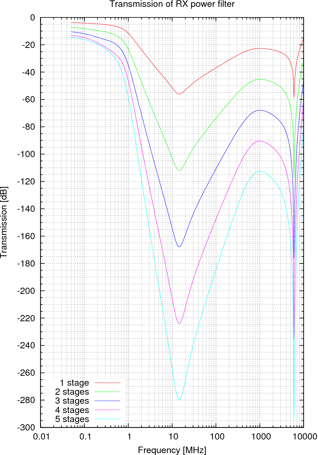
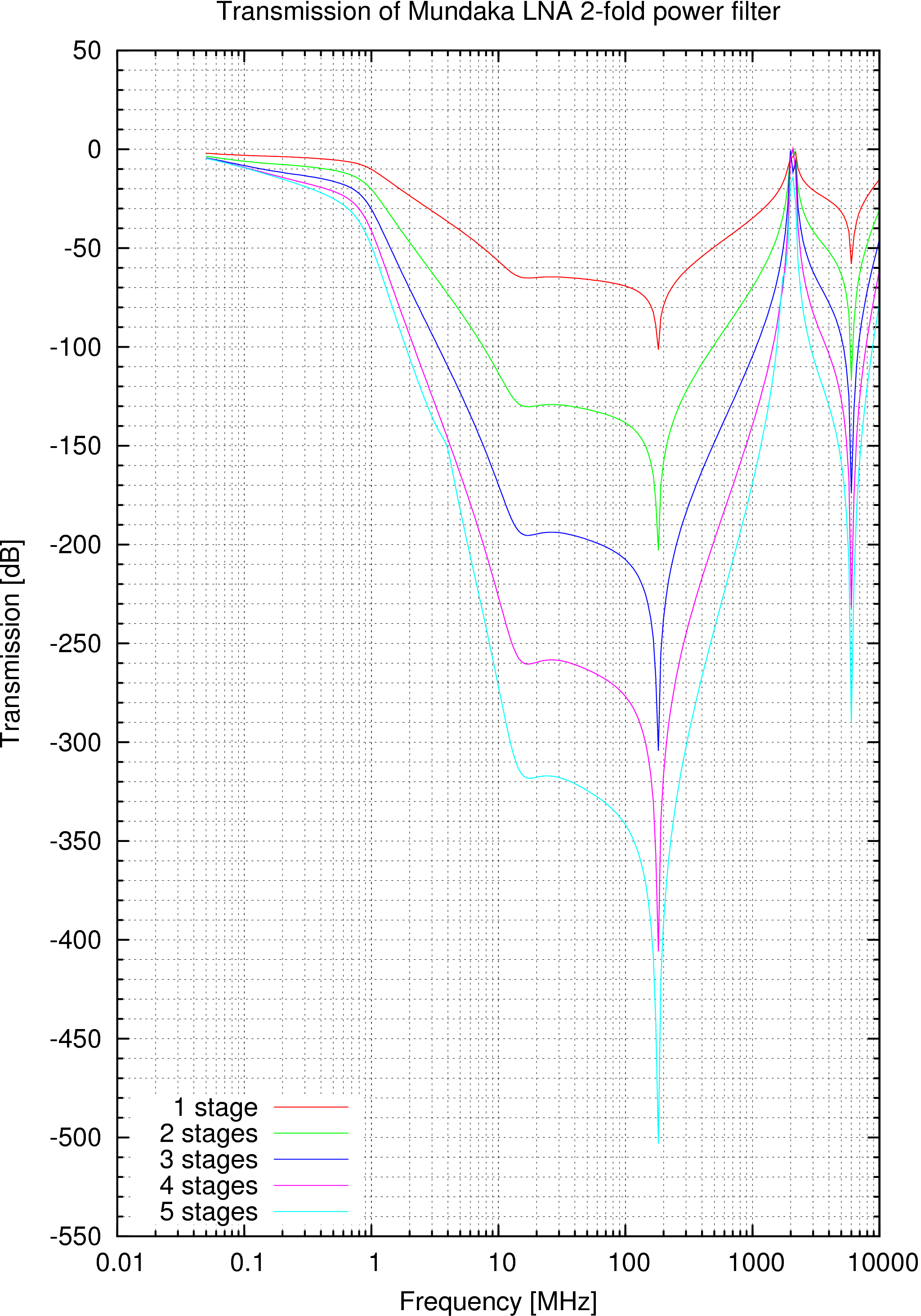
After damping the worst situation happens at about 2GHz with -22dB attenuation and then at 10GHz with about -15dB. That's a usable filter. The 15nH coil can be made from 17mm of 0.3mm dia wire (see calculator). |
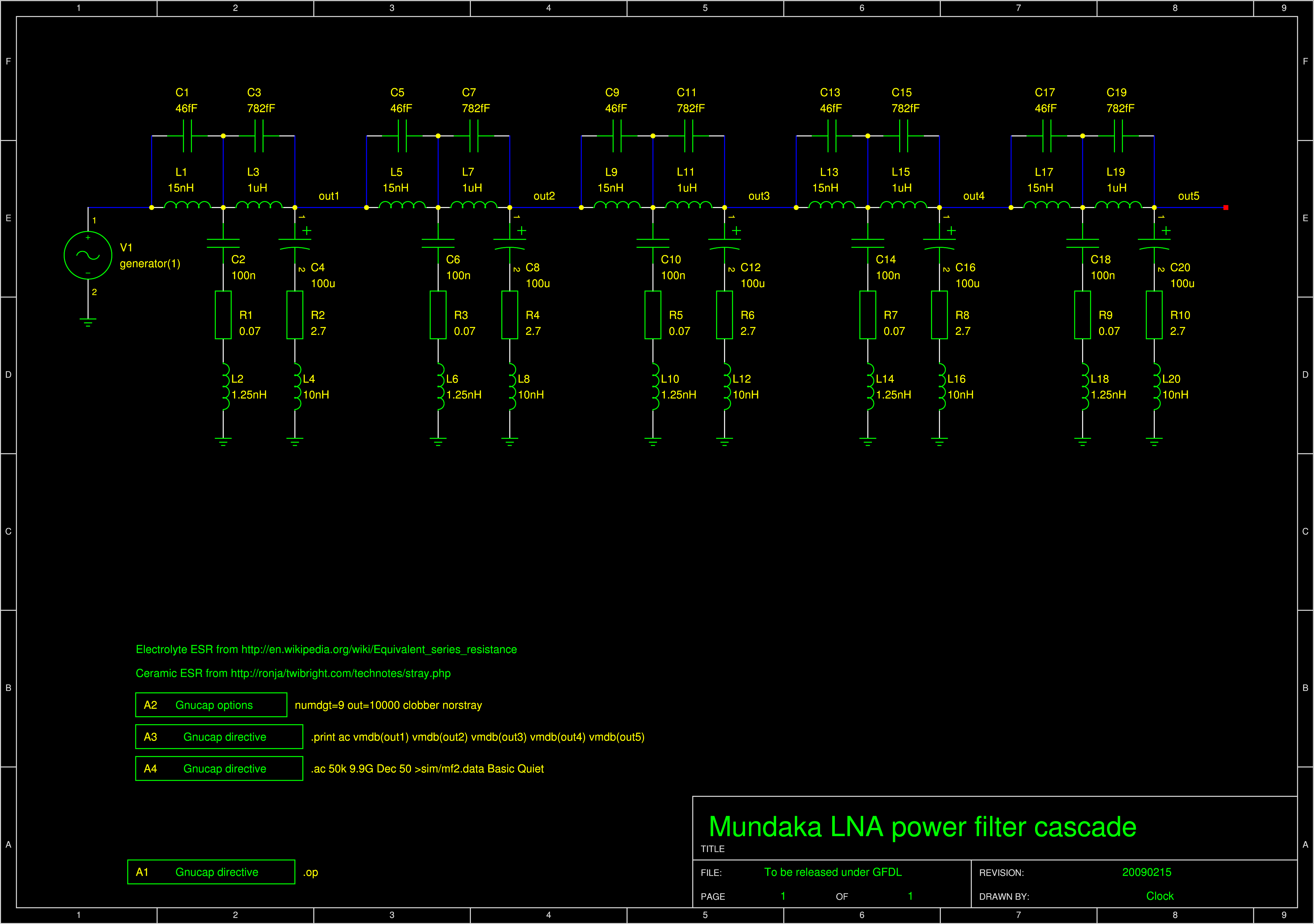
| Each stage consists of HF half (left) and LF half (right). | |||||||||||||||||||||||||||||||||||
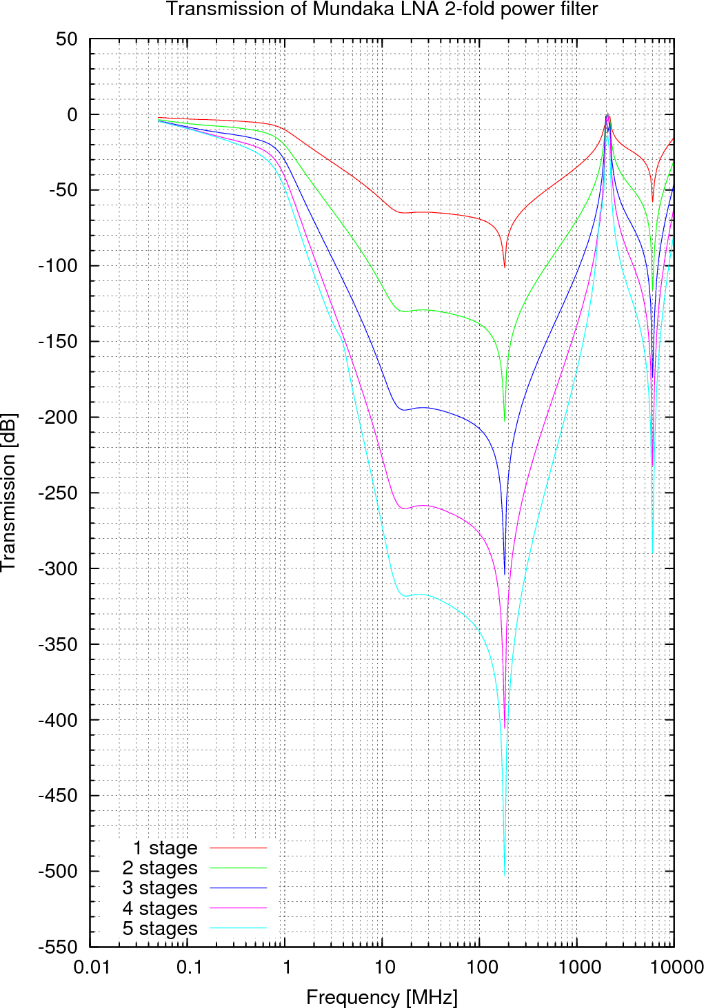
| We are getting a resonance as well. However due to more complicated topology it's difficult to tell which parasitic omponents cause it and how it will react to their changes. Therefore I would abandon this and keep the first filter. |
The minimum guaranteed gain of BFR90, BFR91 or BF91A is min. 25. Each limitter stage runs at 5mA. The governing voltage on the emitter resistors is 1.1V, let's allow a 5% drop to 1V in worst case resulting in 1.05V and 4.75mA. That's 55mV of voltage drop along all the resistors and 18mV per resistor. The max. currents through individual resistors are: 200uA, 400uA, 600uA. The resistances are then 90, 45 and 30 Ohm. These numbers are rather low so let's round up: 100, 47 and 33.
The last resistor - 33 - will be formed by a voltage divider. At the bottom of the divider there will be a diode to temperature compensate the Vbe of the current source transistors. The divider will be fed from 5V regulated. The resistor ratio in the divider has to be 1:2.9 then. THe resistors should be 128.7 and 44.3 which don't exist. Let's take 120 and 47. That gives 1.15 and we need 1.1. 39 at the bottom would give 39. What resistance does the top resistor have to have when the bottom is 47 to get 1.1V? 136.3. Let's put 120 and 15 in series: 135. That gives 1.11V.
The situation with the differential pair power supply is the same because the total current consumed is the same. Just the tolerance doesn't have to be so tight. On the current supply we allow 55mV of drop, let's allow 220mV here. The resistors then will be 390, 180, and 120.
The regulator produces some LF current noise I have seen on the oscilloscope when it was blocked with 100nF only. Let's put a 10uF there to lower it.
6nH of a TMD 100nF capacitor have 377 Ohm at 10GHz so it stops filtering. Therefore we have to use SMD capacitors that have only 78 Ohm. That's still not star performance. Therefore I will insert 15nH which makes 942 Ohm at 10GHz. Doesn't it cause resonation? The element impedance of 15nH and 100nF is sqrt(L/C)=0.38Ohm, therefore critical damping in series is 0.8 Ohm. The circuits will be extremely overdamped.
Now those 15nH will resonate with the 0.35pF parasitic of the resistors. The frequency is 6.9GHz, element impedance 207 Ohm. Parallel critical damping is 103 Ohm. Our current source circuit will be either critically damped (100 Ohm) or overdamped.
Unfortunately this doesn't hold for the differential limitter circuit. Therefore I will just reduce the resistor values there to all 100 Ohm.
Unfortunately the power consumption of the divider will be 23mA that's too much. For that I will employ BC547C. The BC547C has min. 420 gain. Therefore I will multiply the resistors by 47, istead of 33 Ohm combined resistance I will want 1.5k. Now the diode drop on the BC547C has to be compensated by additional diode in series. The voltage above the diodes is not 1.1V anymore but only 0.4V. Now how to make 0.4V from 5-2*0.7=3.6V with combined resistance of 1.5k? The resistor ratio is 1:8. The resistors should be 1.8k and 15k and will give just a bit under 1.8V. But I want a bit more since there is a bit dropout on the filters. Also the didoes have much less current than the transistors. 1.8k and 12k give 1.87V.
Unfortunately there is only 0.339V instead of 1.1 on the 220 Ohm resistor. The circuit is wrongly calculated. But at least I know the dropouts: 0.74V BFR91A, 0.53V BC547C, 1.104V both diodes.
Now there should be 2.37 on the base of BC547C. We want 1.5kOhm combined resistance that means 4.62 top resistor and 2.22 bottom. If we take 4.7 and 2.2, then we get 1.098 on the 220 Ohm resistor.
With regulator at 4.95V and unavailable 2.2k replaced with 1.8k+390 Ohm the 220 Ohm resistor now has 1.05 which is 50mV too low. With 3k9 instead of 4k7 it would be 139mV too high.
The BFR91A has emission coefficient 1.51 and BC547 has 1.58, 1N4148 has 1.906. Because of this 2.2k:4.7k ratio, I have to actually employ 3 BC547Cs that approximates the temperature drift the best. The resistors may need a readjustment to get the proper voltage on the current sources. I will do it practically.
This is too complicated and due to varying voltage drops on manufactured transistors I think this will produce inconsistent results. Therefore I will use an opamp. CA3240 because it's already 2x used and it has suitable temp range and capability to go near lower rail. Unfortunately it has 8mA power consumption (both opamps) but I guess we have to live with it, the benefits outweight this disadvantage.
I will use 10k in the emitter of the feedback transistor so the current going through it is 5mA*220/10k=110 uA to save power. With NE=1.51 this makes 59mV difference. I need exactly 1100mV on the 220 Ohm resistor to get 5mA. I need 1159mV on the + input of the opamp. Since the opamp has input resistance typ. 1500 MOhm, I will use divider resistance around a megaohm. This will consume only 5uA current. The upper resistor will be 1MOhm. The lower has to be 1 Mohm/(5/1.159-1)=301.7 kOhm. I will use 270k and 33k to get 303k. This will make 1162mV instead of 1159, an error of 3mV. The opamp has a typical offset of 2mV.

 Contact, support: Clock
on the Internet Relay Chat.© 1998-2016 Karel ‘Clock’ Kulhavý et al..
Contact, support: Clock
on the Internet Relay Chat.© 1998-2016 Karel ‘Clock’ Kulhavý et al.. 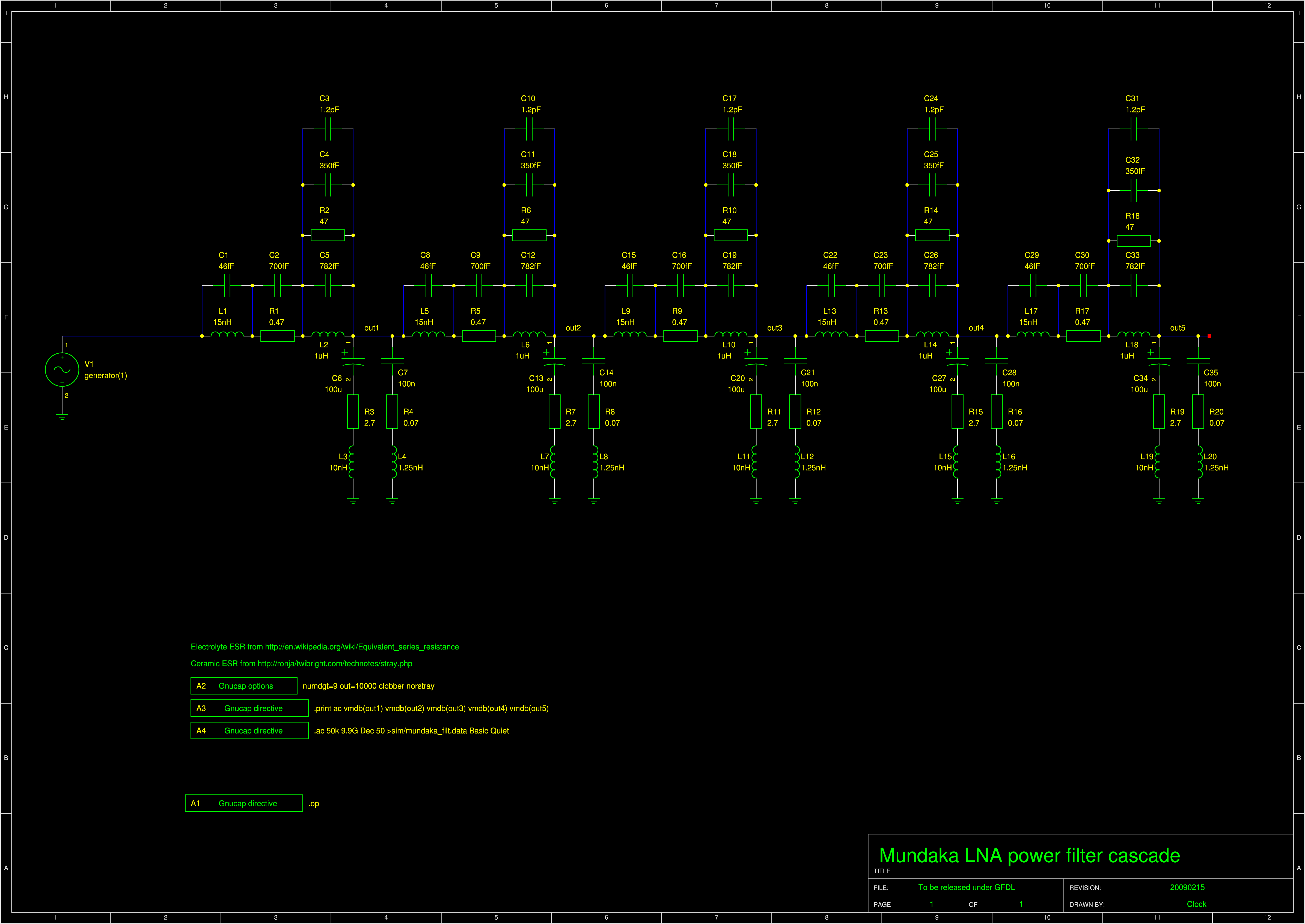