![Gallery[1176]](http://images.twibright.com/tns/lvl2/1176.jpg) |  | What we are going to buildWe are going to:
- Build one 1.5 meter long power exchange cable
(W2-PWR)
- Build one 0.6 meter long RSSI cable (W5-RSSI)
- Equip the signal cables(s) (W1, W2, W5) with connectors (W4 and DE9).
- Attach a W3-PROT lightning protection cable attached to W2-PWR.
| |
|
|
Purpose of the cablesPower exchange cable (W2-PWR) allows
both optical heads to share electrical power. The optical heads take electrical
power from shields of the signal cable(s). Shield of RX signal cable (W1-RX)
carries +12V and the shield of the other signal cable (W1-TX) carries 0V
(Ground, GND).
Some connectors within Ronja 10M Tetrapolis/Inferno system are made of pieces of
thick copper wire (W4), some are DE9.
W3-PROT lightning protection cable protects your home electric installation
from
a fire hazard if lightning strikes directly into the shield of signal
cables (W1) laid on the roof. TV antenna and TV set are protected the same
way. |
|
|
CuttingCut the following wires:| Designation | Number of pieces | Length | Thickness (crosssection area in mm^2) | Solid Wire/Stranded | Insulated | Shielded | Number of (inner) conductors |
| W1-TX | 1 | Distance from PC to intended optical head mounting site | | Any | Yes | Yes | 1 |
| W1-RX | 1 | Distance from PC to intended optical head mounting site | | Any | Yes | Yes | 1 |
| W2-PWR | 1 | 1.5m | | Any | Yes | Yes | 1 |
| W3-PROT | 1 | 1m | 1 | Stranded | Yes | No | 1 |
| W4-STUB | 12 | 29mm | 4 | Solid Wire | Any | No | 1 |
| W5-RSSI | 1 | 0.6m | | Any | Yes | Yes | 1
|
|
|
|
|
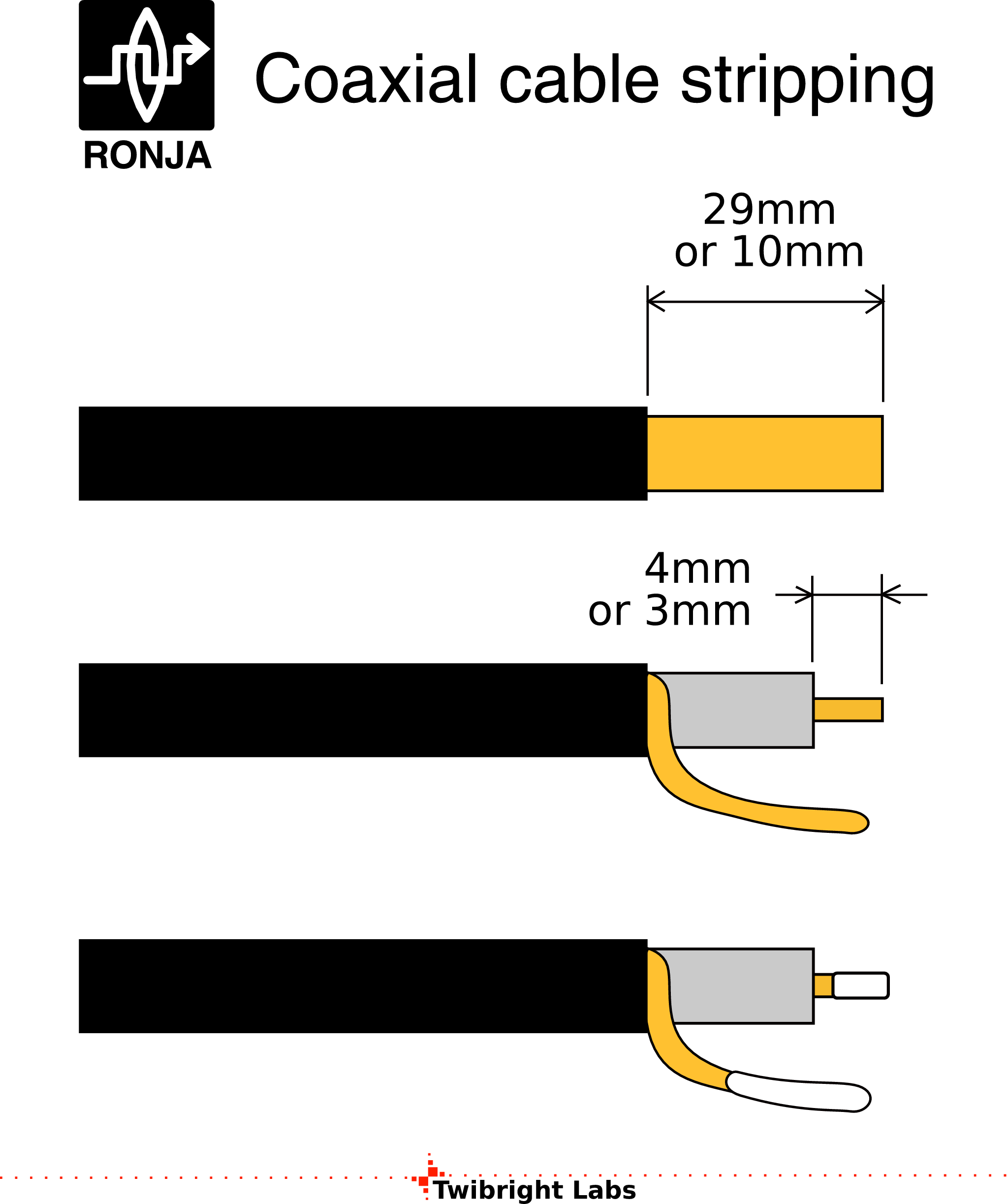
Stripping
The W1 and W2 will be stripped asymmetrically. Let's call the ends
short and long end.
Strip all the wires:
| Wire insulation ID | Length |
| (W1 long end, W2 long end, W5) outer insulation | 29mm |
| (W1 long end, W2 long end, W5) inner insulation | 4mm |
| (W1 short end, W2 short end) outer insulation | 10mm |
| (W1 short end, W2 short end) inner insulation | 3mm |
| W3-PROT | 10mm |
| W4 | Remove all insulation |
When stripping the outer insulation, take care not to cut the thin wires
of the shields.
Strip 10mm off W2-PWR outer insulation in the middle, so that the shield becomes accessible.
![Gallery[1172]](http://images.twibright.com/tns/lvl1/1172.jpg) |
|
|
Covering with solderTwist all visible stranded copper up. Cover the ends of the conductors with solder:
| Wire ID | Length of solder coverage |
| W1, W2, W5 | 4mm |
| W3-PROT | 10mm |
| W4 | 4mm in the middle of the stub |
Cover the stripped place in the middle of W2-PWR with solder too. Solder up
one end of W3-PROT to this place.
|
|
|
|
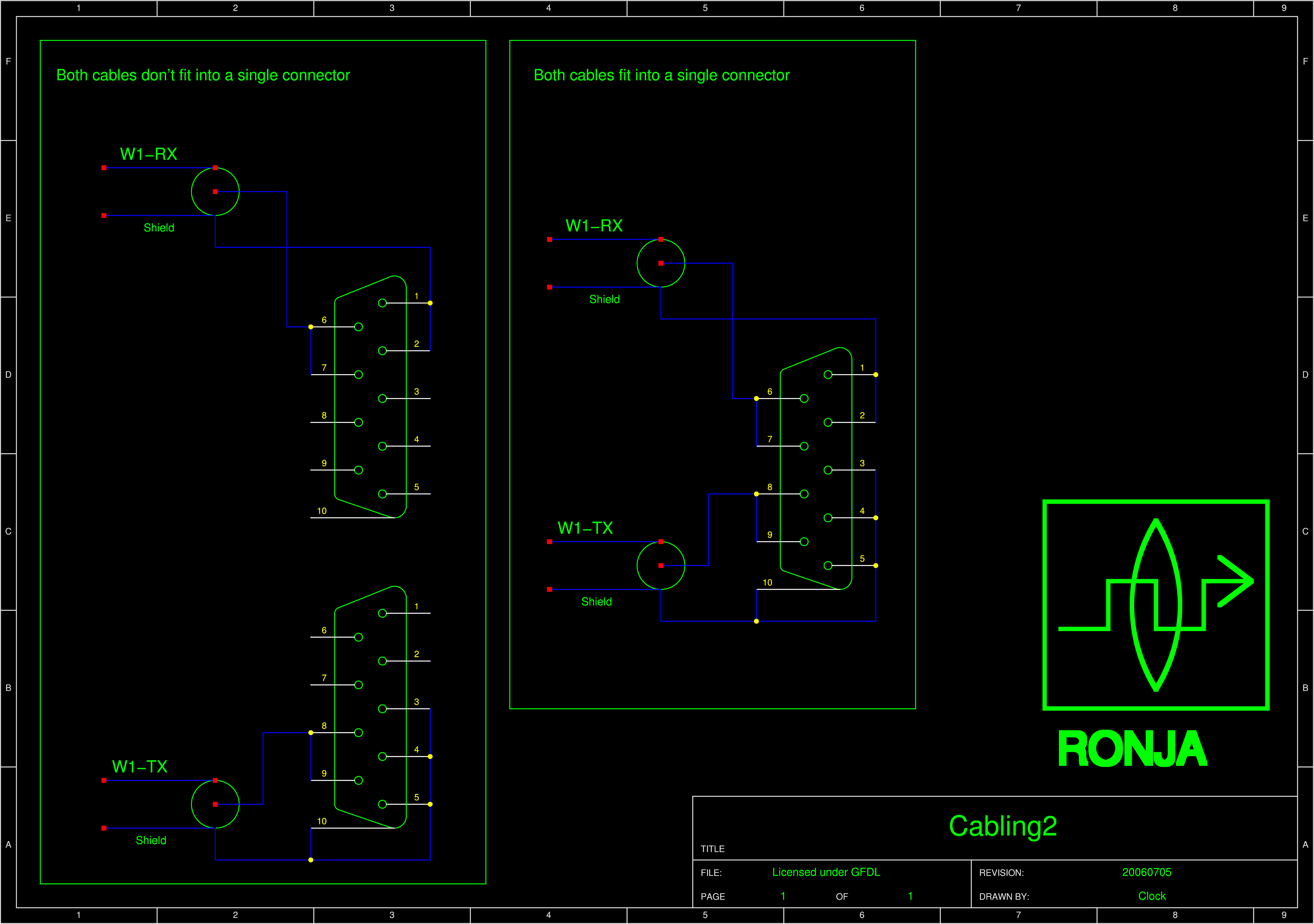
Soldering the DE9 connectors
Solder one or two DE9 connectors on the W1- cables, depending on whether
two cables fit into one enclosure or not. Use the thin (0.7mm^2) hard copper
wire to interconnect the pins and the shell. Make sure the connection to the
shell will not prevent cover installation. |
|
|
|
|
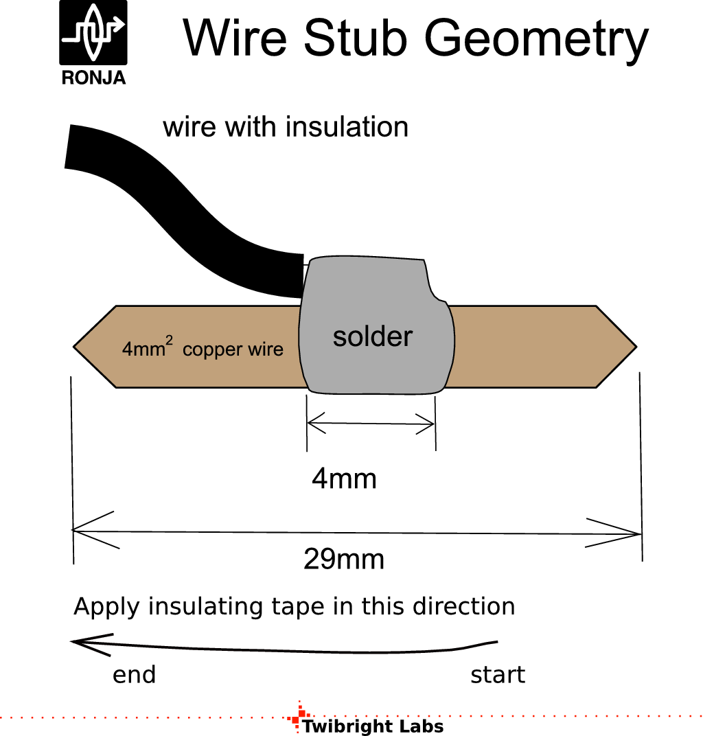
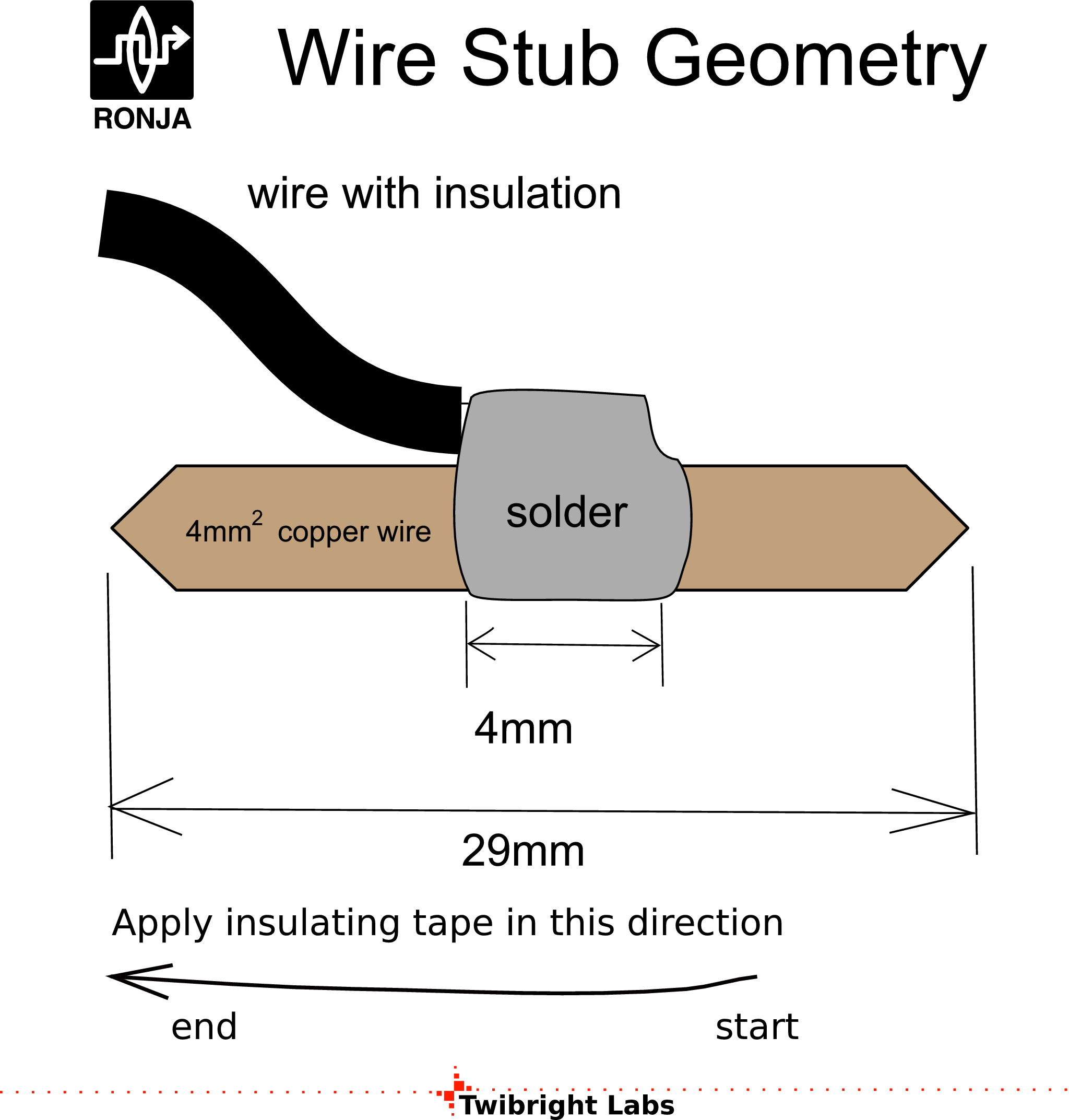
Ends
Solder eyelet on the single end of W3-PROT.
Solder stubs (W4)
on all free ends of W1, W2, and W5 according to the drawing.
|
|
|
| Conductor designator | Colour | Function |
| W1-RX shield | Red | +12V |
| W1-RX inner | Blue | Signal |
| W1-TX shield | Black | 0V (GND) |
| W1-TX inner | Blue | Signal |
| W2-PWR shield | Black | 0V (GND) |
| W2-PWR inner | Red | +12V |
| W3-PROT | Black | Earth protection |
| W5-RSSI shield | Black | 0V (GND) |
| W5-RSSI inner | Blue | RSSI voltage |
|
InsulationWrap up (insulate) the soldered joints with coloured duct tape
according to the table. Use enough
tape to reinforce the ends of the cable mechanically too (to prevent it
from breaking off during repeated bending).
|
|
|

 Contact, support: Clock
on the Internet Relay Chat.© 1998-2016 Karel ‘Clock’ Kulhavý et al..
Contact, support: Clock
on the Internet Relay Chat.© 1998-2016 Karel ‘Clock’ Kulhavý et al.. 
![Gallery[1c3d]](http://images.twibright.com/tns/lvl1/1c3d.jpg)
![Gallery[1178]](http://images.twibright.com/tns/lvl1/1178.jpg)
![Gallery[1173]](http://images.twibright.com/tns/lvl1/1173.jpg)
![Gallery[115b]](http://images.twibright.com/tns/lvl1/115b.jpg)
![Gallery[117a]](http://images.twibright.com/tns/lvl1/117a.jpg)
![Gallery[13ff]](http://images.twibright.com/tns/lvl1/13ff.jpg)
![Gallery[13b7]](http://images.twibright.com/tns/lvl1/13b7.jpg)
![Gallery[1162]](http://images.twibright.com/tns/lvl1/1162.jpg)
![Gallery[1400]](http://images.twibright.com/tns/lvl1/1400.jpg)
![Gallery[13b8]](http://images.twibright.com/tns/lvl1/13b8.jpg)
![Gallery[1c3e]](http://images.twibright.com/tns/lvl1/1c3e.jpg)
![Gallery[117b]](http://images.twibright.com/tns/lvl1/117b.jpg)
![Gallery[1176]](http://images.twibright.com/tns/lvl1/1176.jpg)