 |
We are going to build Audiofire: a metal box with
holes, grommet, wire nut and electronics.
|
|
|
![Gallery[16b2]](http://images.twibright.com/tns/lvl2/16b2.jpg)
|
Soldering bottom lidSolder bottom lid
to the body using
soldering iron, solder and rosin flux. |
|
|
![Gallery[1628]](http://images.twibright.com/tns/lvl2/1628.jpg)
|
Contact flaps
- Make contact flaps using tin scissors on rim of the lid
- 1 cut on shorter edge and 2 on longer
- Shape them so that every flap has good contact
|
|
|
|
|
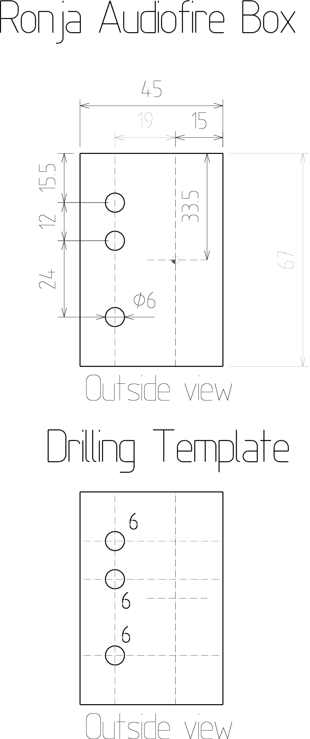
There are two possibilities how to drill out the box. First one is using
a
calibrated printer,
printing out a template and gluing the template on a tin.
The second one is measuring everything by hand. |
|
|
|
|
Option 1: Drilling
templatePrint out this drawings, cut out the drilling
template and glue on the tin box. ![Gallery[1624]](http://images.twibright.com/tns/lvl1/1624.jpg)
|
|
|
|
|
Option 1: Drilling
Drill out holes on the template. Use the wire nut as template for it's
mounting holes. During drilling use the M3 bolts and possibly also
nuts to hold down the nut in already drilled holes.
After drilling, soak the template off in water and throw away. |
|
|
|
|
Option 2: making the
box with manual measurementsMake the box according to the plan. Use
hard stylus or thin marker for nonporous surfaces for drawing lines. Use square
for maintaining perpendicularity and centre punch for making centres of holes. |
|
|
![Gallery[1636]](http://images.twibright.com/tns/lvl2/1636.jpg)
|
BushingsInstall three 4mm grommets
into the 6mm holes. |
|
|
|
|
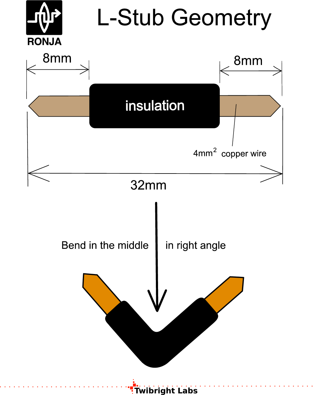
Making L stubs
Make 3 L-stubs stubs according to the picture. Cut also 3 20mm long
straight bare pieces from the same wire. |
|
|
![Gallery[163a]](http://images.twibright.com/tns/lvl2/163a.jpg)
|
Installing wire stubsInstall 3 insulated L-shaped
wire stubs into the grommets. Prepare straight uninsulated wire
stubs. |
|
|
![Gallery[163d]](http://images.twibright.com/tns/lvl2/163d.jpg)
|
Mounting wire nutMount the wire nut. Wrench is
5.5mm. Use 5 M3x15 bolts and 5 M3 washers and 5 M3 nuts and tighten.
Install ends of L stubs into the wire nut and tighten.
Insert and tighten the two 20mm long uninsulated straight wire stubs into the
remaining slots of the wire nut on the same side as the previously
installed L-stubs. |
|
|
![Gallery[1641]](http://images.twibright.com/tns/lvl2/1641.jpg)
|
Soldering down straight stubs
Solder down the straight wires onto the tin box. |
|
|
|
|
Color bandsApply color bands with shown colors
made from duct tape. Remember existence of this drawing for future reference
when soldering the circuit inside.
Note: the photo shows completed Audiofire, ignore the label. |
|
|
|
|
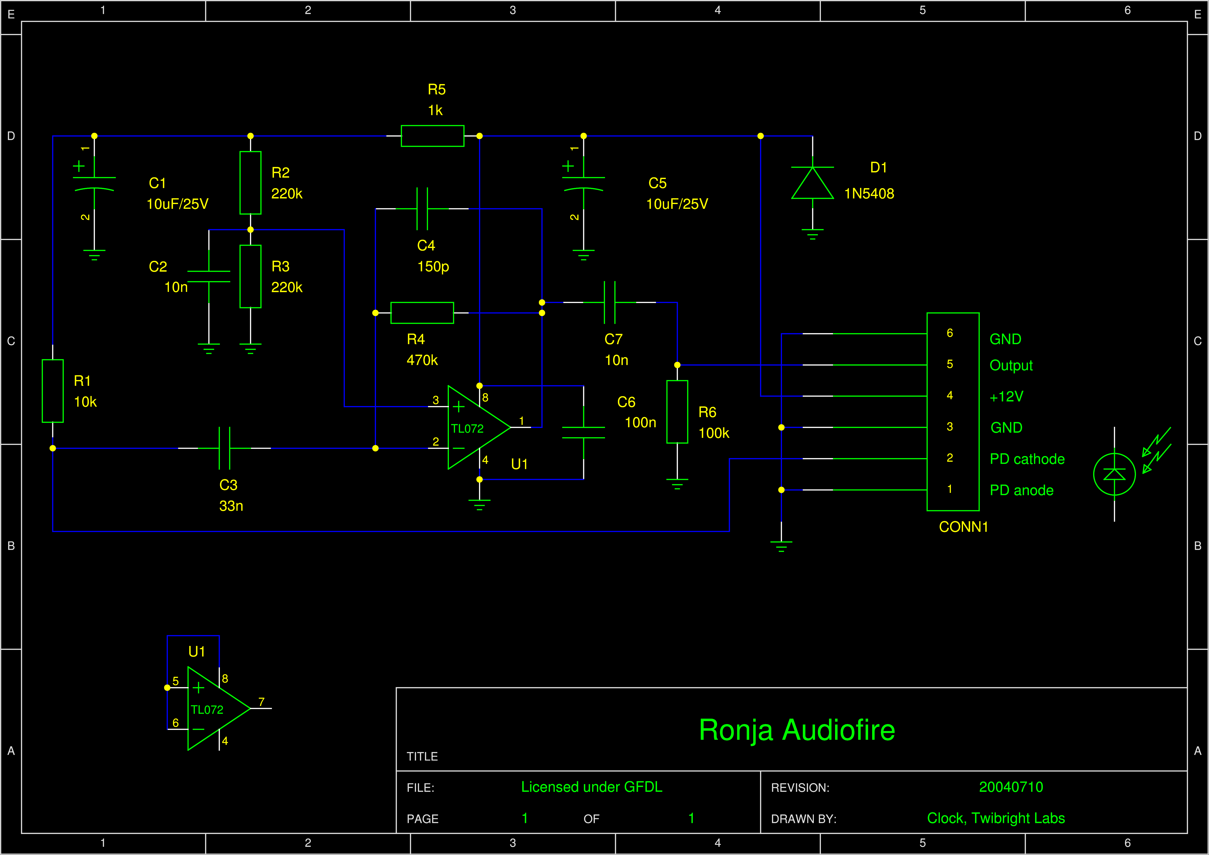
We are going to solder an airwire construction.
The IC will be glued down on it's back. The interconnections will be
soldered using a hard wire, solder and rosin flux. A transformer soldering iron
(the one with the loop) or regulated-temperature iron is used for this.
FIXME: sem dat obrazky Audiofire.
|
|
|
| Write on chip's bottom side it's designation again (use paper
stickers). Glue chip down on it's back somewhere in the middle of the box. |
|
|
|
Soldering
Solder in all the parts according to the schematic in this order:
- U1
- IC blocking capacitors: C1, C2, C3
- The rest
|
|
|
Correctness checkTake the Audiofire and inspect it completely.
- Left-out components
- Left-out wires
- Wires leading somewhere else than they should lead
- Correct values of passive components
- Correct IC type
- Correct orientation of IC
- Correct orientation of diodes.
- Correct orientation of polarized capacitor
|
|
|
|
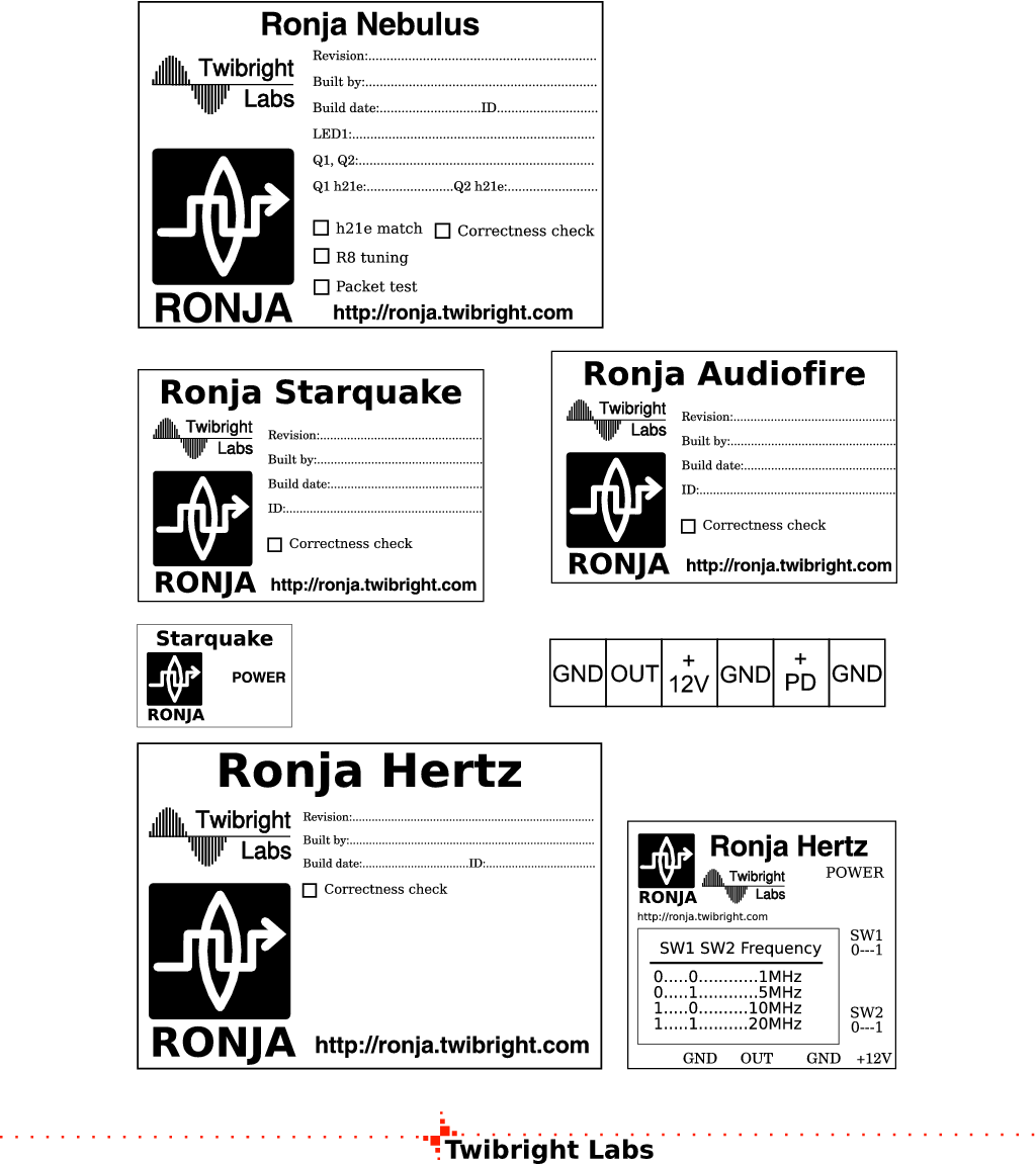
Labels
Print out the Audiofire labels. Stick the big label on outer side of
the lid and fill in. Strick the strip label on the other longer side
than the colour strips are so that when the wire nut is up, you can
read the letters on the strip label. |
|
|
| Print out the small schematic (see the
Schematic section above) and glue on the inner side of the lid. Cross
over any component that is replaced by an equivalent and inscribe the true
equivalent type. |
|

 Contact, support: Clock
on the Internet Relay Chat.© 1998-2016 Karel ‘Clock’ Kulhavý et al..
Contact, support: Clock
on the Internet Relay Chat.© 1998-2016 Karel ‘Clock’ Kulhavý et al.. ![Gallery[1624]](http://images.twibright.com/tns/lvl0/1624.jpg)
![Gallery[1625]](http://images.twibright.com/tns/lvl0/1625.jpg)
![Gallery[16b2]](http://images.twibright.com/tns/lvl0/16b2.jpg)
![Gallery[1627]](http://images.twibright.com/tns/lvl0/1627.jpg)
![Gallery[1628]](http://images.twibright.com/tns/lvl0/1628.jpg)
![Gallery[1629]](http://images.twibright.com/tns/lvl0/1629.jpg)
![Gallery[162a]](http://images.twibright.com/tns/lvl0/162a.jpg)
![Gallery[162b]](http://images.twibright.com/tns/lvl0/162b.jpg)
![Gallery[162c]](http://images.twibright.com/tns/lvl0/162c.jpg)
![Gallery[162d]](http://images.twibright.com/tns/lvl0/162d.jpg)
![Gallery[162f]](http://images.twibright.com/tns/lvl0/162f.jpg)
![Gallery[1630]](http://images.twibright.com/tns/lvl0/1630.jpg)
![Gallery[1631]](http://images.twibright.com/tns/lvl0/1631.jpg)
![Gallery[1632]](http://images.twibright.com/tns/lvl0/1632.jpg)
![Gallery[1635]](http://images.twibright.com/tns/lvl0/1635.jpg)
![Gallery[1636]](http://images.twibright.com/tns/lvl0/1636.jpg)
![Gallery[1637]](http://images.twibright.com/tns/lvl0/1637.jpg)
![Gallery[1638]](http://images.twibright.com/tns/lvl0/1638.jpg)
![Gallery[1639]](http://images.twibright.com/tns/lvl0/1639.jpg)
![Gallery[163a]](http://images.twibright.com/tns/lvl0/163a.jpg)
![Gallery[163b]](http://images.twibright.com/tns/lvl0/163b.jpg)
![Gallery[163c]](http://images.twibright.com/tns/lvl0/163c.jpg)
![Gallery[163d]](http://images.twibright.com/tns/lvl0/163d.jpg)
![Gallery[163e]](http://images.twibright.com/tns/lvl0/163e.jpg)
![Gallery[163f]](http://images.twibright.com/tns/lvl0/163f.jpg)
![Gallery[1640]](http://images.twibright.com/tns/lvl0/1640.jpg)
![Gallery[1641]](http://images.twibright.com/tns/lvl0/1641.jpg)
![Gallery[1642]](http://images.twibright.com/tns/lvl0/1642.jpg)
![Gallery[1643]](http://images.twibright.com/tns/lvl0/1643.jpg)
![Gallery[1644]](http://images.twibright.com/tns/lvl0/1644.jpg)
![Gallery[1645]](http://images.twibright.com/tns/lvl0/1645.jpg)
![Gallery[1646]](http://images.twibright.com/tns/lvl0/1646.jpg)
![Gallery[16ae]](http://images.twibright.com/tns/lvl0/16ae.jpg)
![Gallery[1625]](http://images.twibright.com/tns/lvl1/1625.jpg)
![Gallery[1630]](http://images.twibright.com/tns/lvl1/1630.jpg)
![Gallery[1632]](http://images.twibright.com/tns/lvl1/1632.jpg)
![Gallery[169c]](http://images.twibright.com/tns/lvl1/169c.jpg)
![Gallery[1638]](http://images.twibright.com/tns/lvl1/1638.jpg)
![Gallery[163e]](http://images.twibright.com/tns/lvl1/163e.jpg)
![Gallery[1640]](http://images.twibright.com/tns/lvl1/1640.jpg)
![Gallery[1641]](http://images.twibright.com/tns/lvl1/1641.jpg)

![Gallery[1643]](http://images.twibright.com/tns/lvl1/1643.jpg)
![Gallery[1644]](http://images.twibright.com/tns/lvl1/1644.jpg)
![Gallery[16ae]](http://images.twibright.com/tns/lvl1/16ae.jpg)
![Gallery[1642]](http://images.twibright.com/tns/lvl1/1642.jpg)
![Gallery[1645]](http://images.twibright.com/tns/lvl1/1645.jpg)
![Gallery[1646]](http://images.twibright.com/tns/lvl1/1646.jpg)