 |
OverviewWe are going to install the device. Then an aiming will be performed using visible feedback
of the carrier beam from a retroreflector. |
|
|
RX and TX into headsMount the receiver and the transmitter each into one optical head.
Press the tube from the side so that it widens temporarily in the slide space.
Put on the M4 washers on the receiver and transmitter fastening bolts. Insert
both electronic boxes into the tubes and release them. Put on the slide covers
and M4 nuts. Tighten slightly. |
|
|
|
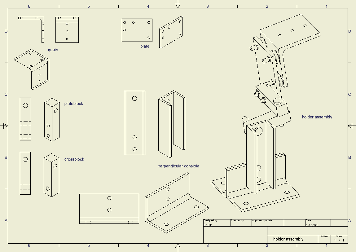
Assembly overviewGet the notion what the holder and console
assembly looks like. This example picture is with Perpendicular console,
but other consoles work the same way: |
|
|
Heads onto holdersMount both optical heads onto the holders using three M6 screws and
three M6 nuts that are attached to each optical head. Put their front caps'
heating cables through the 10.5mm holes in the heels.
The following pictures show heads with holders attached. Note: the first picture is missing plate blocks and cross blocks, the second one the cross blocks only. |
|
 |
WarningIf you are mounting on a chimney make sure the exhaust is not
blocked - people
have died
from that. |
|
|
Protecting the console from lightning - first step
If Ronja is installed on a metal railing or mast which is already lightning protected, scrape off the paint from all points where the console will rest
on the railing or mast.
|
|
Console
Mount the console on the mounting support (wall, railing, chimney etc.). Attach
the holders with the optical heads onto the console using the M10 bolt included
in the console. |
|
Protecting the console from lightning - second step
- If Ronja is installed indoor, skip this box.
- If Ronja is installed on a metal railing or mast which is already properly lightning protected, skip this box.
- Connect the console to the lightning rod conductor of the house using the clamps and lightning conductor included with the console. If the console has 2
non-touching pieces (railing or wall perpendicular console), connect both pieces to the lightning conductor. Before connecting the clamp to the console itself,
scrape off paint at all places where the clamp will touch the console.
Mount the console on the mounting support (wall, railing, chimney etc.).
|
|
|
|
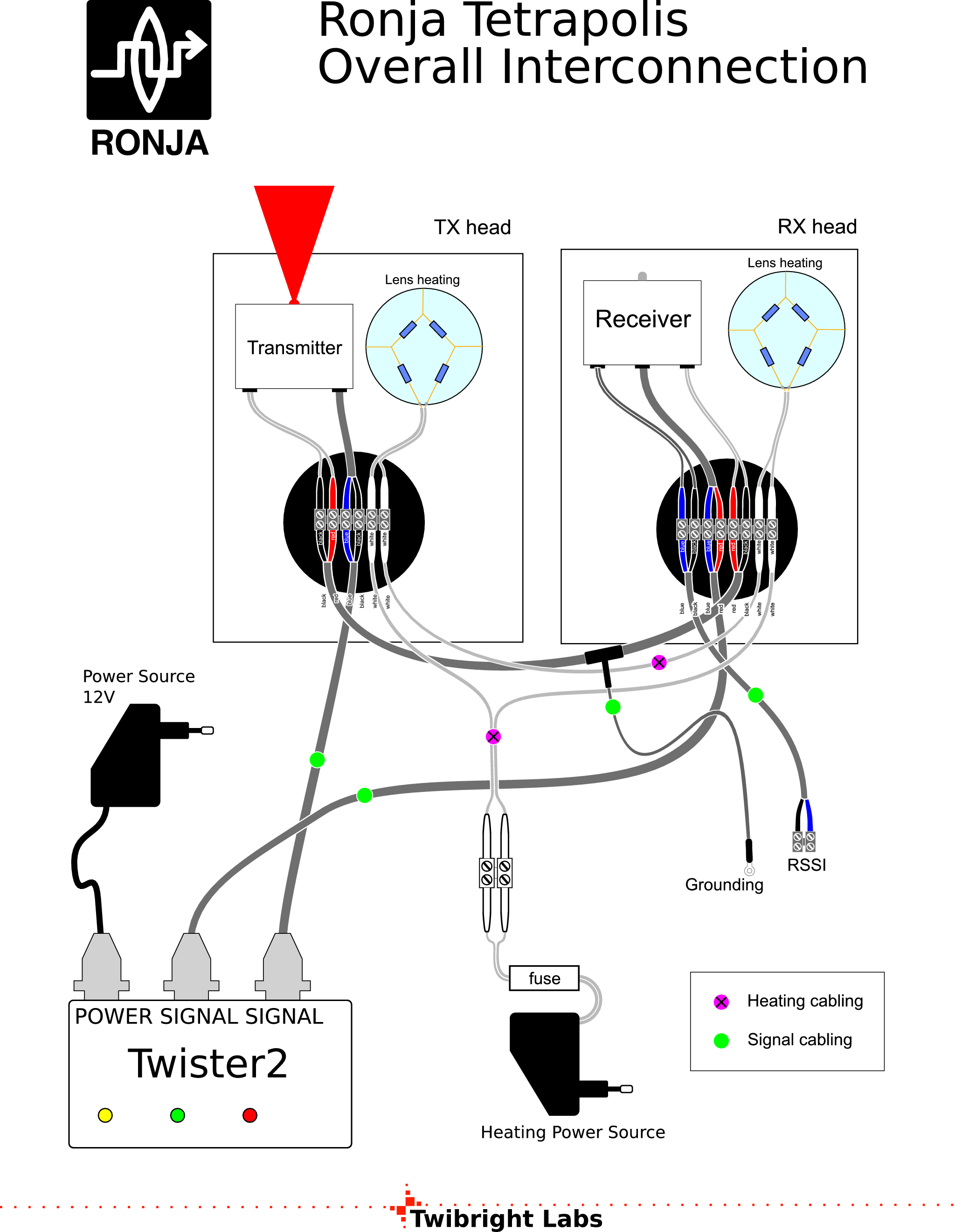
Have for a reference this schematic of a complete Ronja installation for wiring. |
|
|
![Gallery[71c]](http://images.twibright.com/tns/lvl2/71c.jpg)
|
Cables into capsInsert signal cabling, power exchange cable, heating cabling and heating
exchange cable into the rear caps that come with RX and TX and tighten then
down at wire nuts. Connect internal connections to the wire nut:
receiver, transmitter, and heating cable stubs. |
|
|
GroundingConnect power exchange's cable grounding clamp to console grounding
or to a nearby lightning rod conductor or grounded roof tin. Check with a multimeter that
between receiver's and transmitter's M4 bolts protruding through the optical
head and lightning conductor, there is less than 0.2 Ohm resistance. |
|
Signal CablingConnect the signal cabling into Twister2. |
|
Connecting
Plug the Twister2 into your PC or switch.
Set both switches on it to proper position
depending on if you have a PC or a switch. See the label on the Twister2
for details. |
|
Power onTurn the PC or switch on.
Plug the Tetrapolis Power Source into wall outlet.
The transmitter should shine it's beam at this moment. If it doesn't, something
is electrically wrong and check all connections again. |
|
Heating
Prepare a multimeter on 20V DC or AC range. Select the range according to the
type of your heating power source.
Conect the heating
cabling into heater transformer 2-terminal wire nut and plug the
transformer into wall socket. Measure voltage on the wire nut immediately.
If it's 0V instead of something resembling heating source's nominal voltage,
then there's a short circuit in the heating wiring and the fuse has probably
just blown too. |
|
Retroreflector boardIf your track is so long you are going to use more than one
retroreflectors, attach these retroreflectors on a waterproof board. Place them
so that the resulting shape has a low circumference. |
|
RetroreflectorsAttach retroreflector (or retroreflectors on a board, or a car warning triangle) on the receiver or as near
to the receiver as possible, roughly perpendicular to the track. If you are using car warning triangle and the car warning triangle is that type with just outline and hollow middle then slip the triangle over the receiver's optical
head.
A retroreflector
always reflects exactly back from where the light comes. So a moderate tilt
of the retroreflector from future track's axis doesn't
matter.
Number of retroreflectors required (those big red triangular with 16cm side)| Distance | Retroreflectors |
| 450m | 1 |
| 800m | Car warning triangle |
| 900m | 4 |
| 1100m | 6 |
| 1.4km | 9 |
|
|
Silica gelPut one bag of sillica gel into each pipe (beside the box with
electronics, the bag will touch the box with electronics and thermal shield) and close the cap and screw it
down with the screws. |
|
|
|
WarningIf you don't insert silicagel, there will be moisture inside from
two sources - from the original trapped air and then from diffusion through
the silicon sealings. This will result in condensation from inner side
of the lens and link dropouts. It will also corrode the electronics so after
some time (e. g. 1,5 year) all the parts in the electronics suddenly become
unreliable and the electronics will have to be thrown away and built again. |
|
|
|
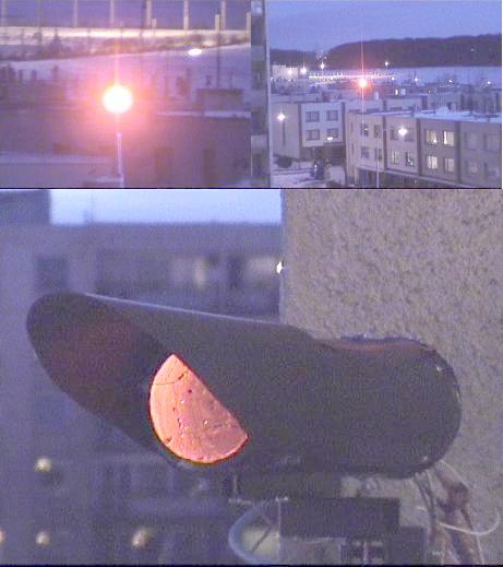
View of a running linkThe picture
shows what the transmitter beam looks like from 260m distance (130mm diameter
transmitter lens) and the big image is the 90mm transmitter in operation from
close, out-of-axis view. |
|
|
Start of aiming
Ask the peer on the other side to switch on his heating (not necessary for
anything yet, but to give it time to heat the lens up).
Tell the peer to switch off his device by unplugging Tetrapolis Power Source
from the wall. |
|
![Gallery[1f84]](http://images.twibright.com/tns/lvl2/1f84.jpg)
|
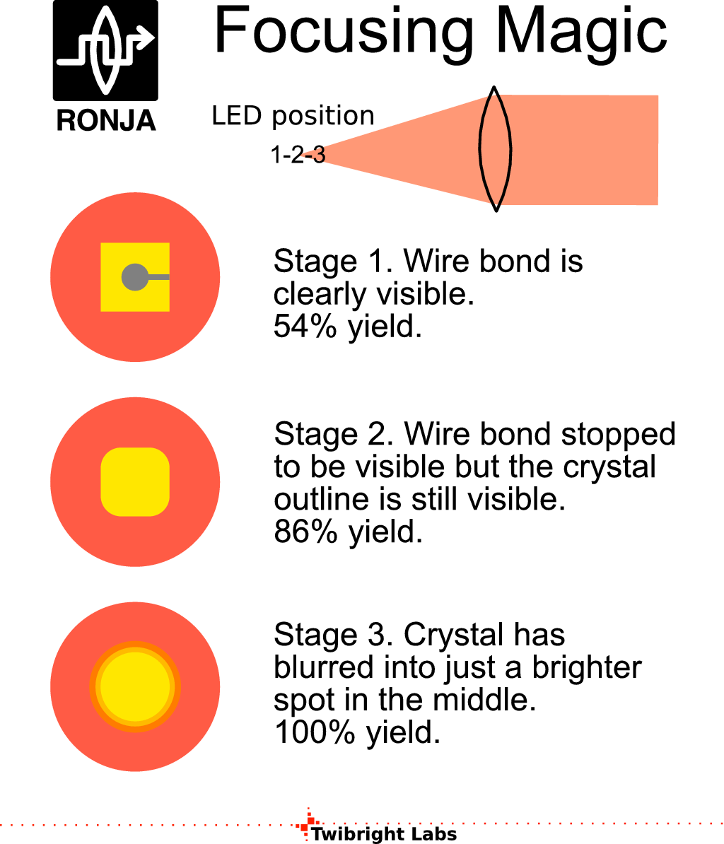
Move the transmitter beam on a distant house, wall etc. Play with the
focus slide path of the transmitter until you see a sharp image of the LED
junction with the wire connected to the crystal. ![Gallery[1f83]](http://images.twibright.com/tns/lvl1/1f83.jpg) |
|
|
|
|
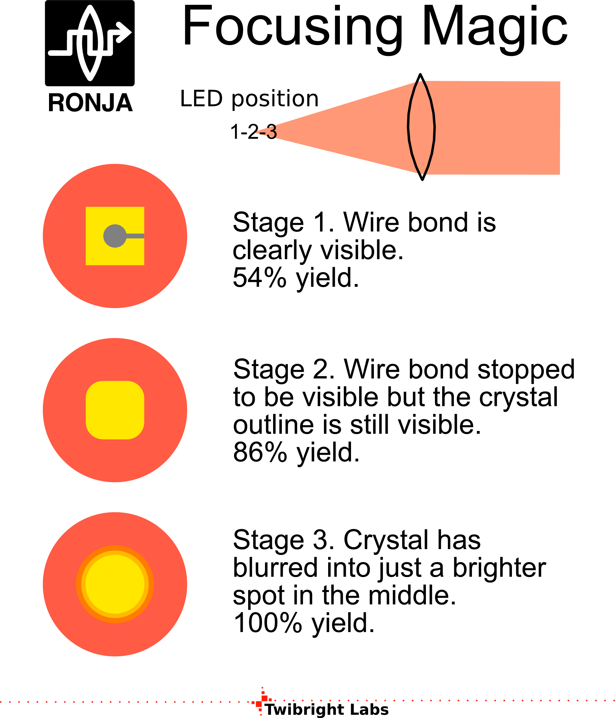
Focusing magicMove the LED
a little bit towards the lens until the wire stops being visible on the
crystal's image. Then move on another bit until the crystal outline stops being
visible. Tighten down the M4 nuts on the TX focus. |
|
|
| Get the retroreflector reflection using the M10 nuts. Then tighten the M10 nuts. If you have got a torque spanner, then the recommended torque is 70Nm. |
|
| Tune for maximum reflection on the retroreflector using the three M8
bolt heads on the fine adjustment. In this stage, observe with your head as
close to the transmitter as possible (the retroreflectors are usually
of high quality). |
|
Other side of the linkGo to the other side. |
|
![Gallery[2c0]](http://images.twibright.com/tns/lvl2/2c0.jpg)
|
Catching signalConnect 200mV DC voltmeter to the
measurement port. Plug the Tetrapolis Power Source into wall.
Put the RX focus into the middle, and catch the signal with rough
adjustment (M10 nuts), then tighten the M10 nuts down. |
|
|
Unable to catch signalIf you are unable to catch the signal at all and you are suspecting the RX to not work, then try remote control. Take a remote control like from TV set and
shine from near into the RX lens. It should make some millivolts. |
|
Fine adjustmentGet the maximum RX level using fine
adjustment. Get the maximum RX level using RX focus. Tighten down the RX focus
(M4 nuts). Get the maximum level using fine adjustment again. The threshold
voltage where the link starts to be able to receive data varies with Q101 gain
and ambient light level and if it's the old receiver with songle BAT4x diode
(lower voltage) or the newer with two ones higher voltage). It may be as low as
0.1mV in the old and as high as 100mV in the new. |
|
Opposite directionPerform the same aiming procedure
in the opposite direction of the free-space link. |
|
IP setupSet up your IP network |
|
|
|
FTP testDownload some 60MB file in one direction using FTP.
It is recommended to switch off the 10240 byte ticks by "ti" command.
Printing them may delay the transfer a bit :) Throughput calculation: Maximum
frame on Ethernet has 1518 MAC bytes plus 8 bytes of preamble plus 1 byte of
postamble (including End Of Frame Delimiter) plus 12 bytes of interframe gap
which is 1539 bytes frame pitch. 18 bytes from 1518 are MAC header which is
1500 bytes of IP data. IP takes another 20 bytes for IP header which is 1480
bytes for TCP datagram. TCP header takes another 20 bytes for it's header so
1460 bytes remain of pure data of the TCP stream. 10,000,000*1460/1539/8 is
1185834.95 bytes per second (1.18583495 MBytes/sec or 1158.04 KiBytes/sec or
1.130 MiBytes/sec.
Here is a summary of data rates on various layers of
the network traffic when trasfering a file via FTP. The calculation is
based on the following assumptions:
- The network stack of both operating systems manage to send and receive packets go back-to-back one after another with no excessive delay (the system is fast enough to keep up with the pace)
- There is no other traffic than tested TCP FTP traffic
- There are no ARP packets :)
- The TCP has negotiated full 1480-byte segment size
- The card support maximum frame size of 1500 bytes. Some advanced cards may support much longer frames.
- The disk is fast enough or the transfer is memory-to-memory
- Both systems are unloaded enough so that the scheduler always manages to prepare the critical process on the line before the various buffers overrun. This
criterium may be corrupted also by system flushing memory cache to the disk.
Check if your measurement
accords to "Pure data (FTP throughput)". However, this is not an authoritative answer, the result may vary depending on system performance. Some advanced cards also permit jumbo frames which may get values with even better bandwidth
utilization.
Data Rate Calculations on Various Layers of The Network Traffic
| Flux class | Bits per second | Bytes per second | Bytes per 1539-byte frame pitch | Bandwidth utilization [%] |
|---|
| Link (Crystal Clock) | 10000000.000
10000.000 k
9765.625 Ki
10.000 M
9.537 Mi | 1250000.000
1250.000 k
1220.703 Ki
1.250 M
1.192 Mi
| 1539 | 100.00
| | Manchester modulated bit slots (RX diode on Twister2 shines) | 9915529.565
9915.530 k
9683.134 Ki
9.916 M
9.456 Mi | 1239441.196
1239.441 k
1210.392 Ki
1.239 M
1.182 Mi
| 1526 | 99.16
| | Ethernet frame data guarded by Frame Check Sum (FCS) -- from DST MAC to FCS inclusively | 9863547.758
9863.548 k
9632.371 Ki
9.864 M
9.407 Mi | 1232943.470
1232.943 k
1204.046 Ki
1.233 M
1.176 Mi
| 1518 | 98.64
| | IP traffic (IP datagrams including IP headers) -- what iptraf shows | 9746588.694
9746.589 k
9518.153 Ki
9.747 M
9.295 Mi | 1218323.587
1218.324 k
1189.769 Ki
1.218 M
1.162 Mi
| 1500 | 97.47
| | TCP traffic (TCP datagrams including TCP headers) | 9616634.178
9616.634 k
9391.244 Ki
9.617 M
9.171 Mi | 1202079.272
1202.079 k
1173.906 Ki
1.202 M
1.146 Mi
| 1480 | 96.17
| | pure data -- what FTP shows | 9486679.662
9486.680 k
9264.336 Ki
9.487 M
9.047 Mi | 1185834.958
1185.835 k
1158.042 Ki
1.186 M
1.131 Mi
| 1460 | 94.87
|
|
|
Full-duplex FTP testLaunch two 60MB FTP data transfer in both directions simultaneously.
This is a real test of the full-duplexity of the link :) The resulting counts
will be a bit lower due to sharing our bandwidth with TCP acknowledgements from the other FTP transfer. |
|
| Look at output of the "ifconfig" command.
"errors" and "frame" should not increase during traffic.
These entries indicate noisy reception. Nonzero numbers in "carrier"
are OK. "collisions" should be zero. "dropped" or
"overruns" indicate your system has problems with performance on such
fast network connections :) |
|
SealingClimb to the roof again and seal all seams on the
tube with the sillicone sealant to be sure no humidity or water will leak
inside. After the sealant solidifies (typically a day), climb there once more
and seal the gaps again. Sealing in a single layer has got a high probability
of failure and water leakage which produces unexpected failure after some time
of troublefree operation and necessity for relatively complicated drying of the
device. |
|
|
|
WarningIf you don't seal the optical head properly, water will probably
get inside. The link may stop working and the electronics may be irreparably
destroyed. See a video. |
|
|
SafetyIf you are not 100% sure with safety of Ronja
installation, call a certified technician to perform a check. The areas may
include:
- Lightning protection safety with accompanied safety from fire hazard
- Power source fusing with accompanied safety from fire hazard
|
|

 Contact, support: Clock
on the Internet Relay Chat.© 1998-2016 Karel ‘Clock’ Kulhavý et al..
Contact, support: Clock
on the Internet Relay Chat.© 1998-2016 Karel ‘Clock’ Kulhavý et al.. ![Gallery[7b9]](http://images.twibright.com/tns/lvl1/7b9.jpg)
![Gallery[31c]](http://images.twibright.com/tns/lvl1/31c.jpg)
![Gallery[32f]](http://images.twibright.com/tns/lvl1/32f.jpg)
![Gallery[574]](http://images.twibright.com/tns/lvl1/574.jpg)

![Gallery[e44]](http://images.twibright.com/tns/lvl1/e44.jpg)
![Gallery[101e]](http://images.twibright.com/tns/lvl1/101e.jpg)
![Gallery[e4c]](http://images.twibright.com/tns/lvl1/e4c.jpg)
![Gallery[e4d]](http://images.twibright.com/tns/lvl1/e4d.jpg)
![Gallery[720]](http://images.twibright.com/tns/lvl1/720.jpg)
![Gallery[721]](http://images.twibright.com/tns/lvl1/721.jpg)
