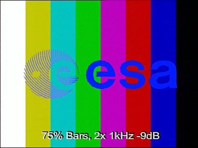
Twibright Labs have developed a family of algorithms to encode ordinary 4:2:0 and 4:2:2 Y'CbCr video with unprecedented colour detail quality. There are three algorithms - Hyperluma 1, Hyperluma 2 and Luminaplex, in order of increasing picture quality. The algorithms solve the so called chroma bleed problem which is a result of the mathematically incorrect idea of chroma subsampling in analog and digital video broadcast, computer video encoding and similar applications. The chroma bleed is best visible as dark contours along edges of bright colours in the picture. It can be seen on the edge between green and magenta and between red and blue on a TV testcard. However it exists for any kind of colour detail, and contributes to overall corruption of the image details.
|
|
The corruption is visible here as a black contour between grean and magenta, between red and blue, on the left edge of the letter e and on most of the letter s. |
|
|

|
|
|
|
5 vertical strips show the quality of individual encoding agorithms compared with the original. Note how the edge corruption decreases from left to right. Use a CRT to view this image properly, LCDs usually display false artifacts on the eges. Nearest neighbour chroma interpolation is assumed in the decoder. 4x magnified. |
|
|

|
|
|
|
The same, but instead of full range, R'G'B' values of only 0x30 and 0xd0 are used. 4x magnified. |
Hyperluma 1 internally simulates the receiver (decoder) of the signal and then adjusts the luma channel until the effect is canceled. The result - these artifacts, which could confuse the viewer in resolving details, are gone.
During chroma subsampling we are presented with 3 pixels, each containing R, G, and B values. We are supposed to produce four Y' (luma) values, one Cb (blue chroma) and one Cr (red chroma value). The original ancient idea of the TV system was that the luma values would describe perceived brightness (luminance), which is perceived by human eye with twice as sharp resolution than the colour information. However, as the luma and chroma are calculated from gamma-corrected (nonlinear) R' G' B' values, luma doesn't represent just luminance (perceived brightness), but is also influenced by the chroma values. To reconstruct luminance properly, both luma and chroma values are necessary - luminance depends on both.
When the chroma values are subsampled and therefore changed, the luminance then suffers too, because depends partially also on the chroma. The first step in ordinary encoding system is to convert R' G' B' values into Y' Cb Cr, the second one is to subsample the Cb Cr. Hyperluma instead converts R' G' B' into gL Cb Cr, where gL is gamma-transformed luminance. gL represents accurately the brightness as perceived by the viewer. In the second step, the Cb and Cr are subsampled as usually. Hyperluma then adds third step, where gL Cb Cr are used to calculate Y' - a luma that would produce with the given Cb Cr the brightness perception that was in the picture at the given pixel position.
The core to the Hyperluma calculation is to solve the following mathematical problem: given Cb, Cr, and gL, what is the Y', that with Cb and Cr produces the given gL?
Because the function transforming Y'CbCr into gL (gamma-transformed luminance) cannot be easily mathematically reversed, the software uses binary division to search for the solution. As this is 8 times slower than the forward transformation and would slow down the video encoding, it precalculates the reverse transformation into an universal lookup table 12.96 megabytes big. This table can be compressed down to just 29kB with bzip and then easily distributed with the program. When the program starts, it loads the table into the RAM, allowing fast video processing without a need to wait on program startup until the lookup table is precalculated.
After I developed the algorithm, published it and consulted with specialists, it came out that the algorithm is patented. That was an impulse to develop Hyperluma 2 and ultimately Luminaplex, which improve the quality even more and don't seem to be covered by any patent.
The problem of Hyperluma 1 is that it removes the problem of nonconstant luminance by providing a constant luminance, however the chrominance stays the same. By the process of chroma filtering and nonlinearities in chroma definition, the chrominance in the picture suffers. This is partially solved by Hyperluma 2.
4:2:2 encoding is analogical. Note that the algorithm doesn't depend on what subsampling filter you use.
Hyperluma 2 improves the chrominance by calculating the chroma not by chroma filtering, but by physically correct photon averaging. The luminance is corrected completely like in Hyperluma 1, the chrominance is corrected partially. But the chrominance correction is not perfect - the luma shift caused by the luma correction by the hyperluma table causes the colours to drift from their ideal values.
Hyperluma 1 and Hyperluma 2 are algorithms of constant luminance. But the viewer doesn't watch the luminance only. He cares also about the chrominance! I took a completely different approach and set a goal to get both constant luminance and constant chrominance. The result is the Twibright Luminaplex algorithm, an algorithm that produces the ultimately correct result.
The ultimate idea of encoding RGB or 4:4:4 Y'CbCr into 4:2:0 or 4:2:2 Y'CbCr is strikingly simple. You want the viewer to see the same on the TV as what is in the input signal. And that's what lead me to the Luminaplex algorithm, the algorithm that provides the ultimate quality.
Sees the same doesn't mean the TV shows the same. The human eye is alleged to have half resolution in colour than in brightness. But how to quantify this, when the error is perceived according to a power function, while the colour mixing goes linearly? I cut this Gordic knot with a simple algorithm that I still believe is accurate. This is what the perceived_error function in the source code calculates:
Note that this algorithm, unlike Hyperluma 1 and 2, are defined with the assumption that the receiver uses a nearest neighbour filter for the chroma upsampling. There is actually no need to use any more complicated filter than this. The transmission chain with Twibright Luminaplex encoder and nearest neighbour decoder preserves the luminance and the chrominance in the passpand of human eye. Some spatial frequency mirrors are generated in the chrominance area above the capability of human eye to discern colours, because the average-4-pixels filter doesn't cut off above the Nyquist frequency well. However it doesn't matter, because human eye cannot see these mirrors anyway.
Running a decoder with more sophisticated chroma filter on a Luminaplex output is not only a waste of CPU time, but also degrades the picture somewhat. The Luminaplex output was optimized for the simplest filter. For example mplayer on png output (where I can study the output exactly) uses this simplest filter.
But what if we need to encode with Twibrigtht Luminaplex for a decoder that uses a more sophisticated filter, like bilinear or even bicubic? Then the task becomes more complicated, but not impossible.
Instead of optimizing blocks 2x2 now we have to optimize the whole picture as a single block, because changing one luma or chroma value influences the errors in several neighbouring pixels. It's the same algorithm, but instead of 6 dimensions we have several hundreds thousands or millions dimensions.
Each iteration we don't have to minimize the global image error, but we need to calculate the error only for those pixels that are influenced in the output by the changed value. The size of this area is given by the size of the filter core in the decoder. It will surely slow down the calculation, several times, depending on the core size. But it can still be practical for one-time encoding of videos for distribution for example on a website or on a DVD. I didn't implement this variant into pix-y4m.c because it would be more complicated and slower and I didn't intend to use it on the Ronja project.
The Luminaplex algorithm is not suitable for broadcast because theoretically one could feed a poisonous picture that would contain a lot of difficult squares that would slow down the decoder and cause a stream dropout. The Hyperluma 2 doesn't have this problem, the execution always takes the same time there.
Some 8-bit R'G'B' triplets are not representable by 8-bit Y'CbCr - example seems to be 192,64,192. In such case Luminaplex sometimes produces some kind of 2x2 dithering to minimize the error. Very slight dithering artifacts on constant edges or constant colours result. If this is not acceptable for some reason, Hyperluma 2 must be used instead. Sometimes the colour transition is so sharp that Y'CbCr would have to go out of range to produce the correct result. It was originally programmed this way but then it came out that mplayer seems to clip Y'CbCr into the 16-235,16-240,16-240 range before processing and the result was horrible - a green tint on black. So I removed this and allowed only Y'CbCr values within the range to be used. This degraded the SNR on the numeric test (below) only by about a decibel, from 45dB to 44dB.
I have made a test with randomly generated pixel content. Such content exercises all possible colour transitions in the linear RGB cube homogenously. The RMS error is calculated for LSB per pixel - if it comes out as N, it means you would need to increase all 8-bit R'G'B' channels in a picture by N to get the same level of perceived error. I also provide a SNR value in dB from this SNR. 0 dB means error excursion of 127.5LSB - the same excursion from the average as the strongest possible signal - white/black bars. 400,000 randomly filled pixel squares were used for each run. Iterations per pixel are indicated, that counts how many times the perceived_error calculation is performed per pixel (from which 0.25 is for evaluation purpose only). The time/pixel is measured on 1.5GHz Pentium M with OpenBSD 4.0, gcc 3.3.5, and optimization flags -g -O2 -fomit-frame-pointer -funroll-loops -fstrength-reduce.
| Algorithm | RMS error [LSB] | SNR [dB] | Time/pixel [usec] | Iterations/pixel |
|---|---|---|---|---|
| Ordinary | 9.075 | 22.95 | 0.20 | 0.25 |
| Hyperluma 1 | 5.635 | 27.09 | 0.18 | 0.25 |
| Hyperluma 2 | 2.800 | 33.17 | 0.18 | 0.25 |
| Luminaplex | 0.731 | 44.83 | 2.01 | 6.96 |
pix-y4m.c and constants.h is the source code. The Hyperluma 1 is disabled in the code. As it is now the code implements Twibright Luminaplex and the inaccessible Hyperluma 1 code is there only for illustration.
Ronja 3D videos which are used to illustrate how to put Ronja together, are now all encoded with the Luminaplex algorithm. It is indicated by a small Luminaplex logo in the upper left corner. I think it was a good idea to develop the Luminaplex algorithm for this application, because the models are brightly coloured for comprehensibility and then the chroma bleed problem is the strongest. The chroma bleed disease attacks details of the picture and people could have problem identifying all those small nuts, bolts and holes in the Ronja models.
As I already mentioned, the Hyperluma 1 algorithm seems to be covered by some patents. Hyperluma 2 and Luminaplex are not, I hope. On January 28, 2007 I published these algorithms and their GPL free software implementation to constitute prior art and to prevent someone from stealing them by patenting them and then being able to prevent people from using this algorithm. I have sent a note to various mailing lists and respectable individuals so a plausible proof of prior art can be constructed to challenge a patent if someone tried to abuse the patent system this way.
This of course applies only in the case the Hyperluma 2 or Luminaplex algorithms doesn't accidentally happen to be already covered by a patent as happened in the case of Hyperluma 1. I didn't conduct a patent search because these are expensive and checked just the patents connected with Hyperluma 1. If you are curious you can conduct a patent search yourself. Should you find a patent that infringes either algorithm, let me know.
Software patents are harmful for software development, especially free software. If you look into some public patent database you can see the patent system is full of simple algorithms performing simple tasks, effectively banning free usage of some independently invented innovative ideas.

 Contact, support: Clock
on the Internet Relay Chat.© 1998-2016 Karel ‘Clock’ Kulhavý et al..
Contact, support: Clock
on the Internet Relay Chat.© 1998-2016 Karel ‘Clock’ Kulhavý et al..