 |
We are going to make a welded console that looks like
this, except
the short supports are shorter and the
beam is rotated by 90 degrees
|
|
|
|
|
|
|
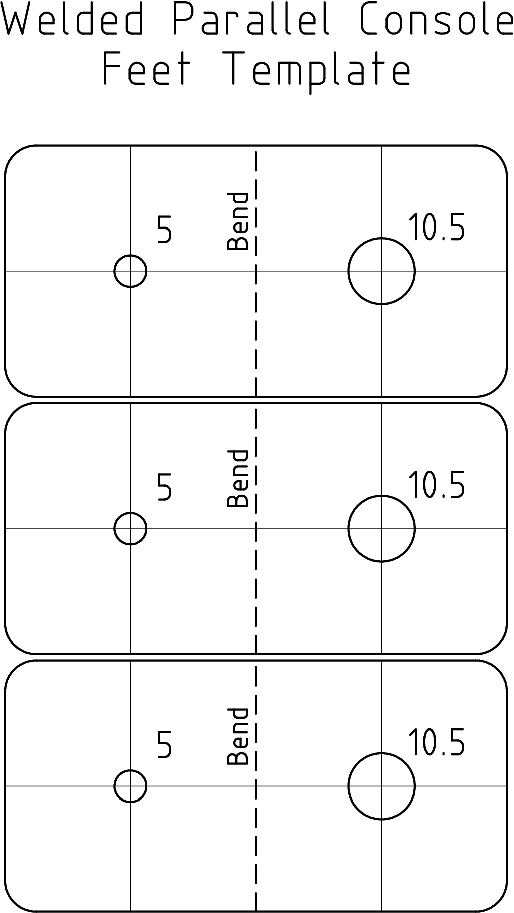
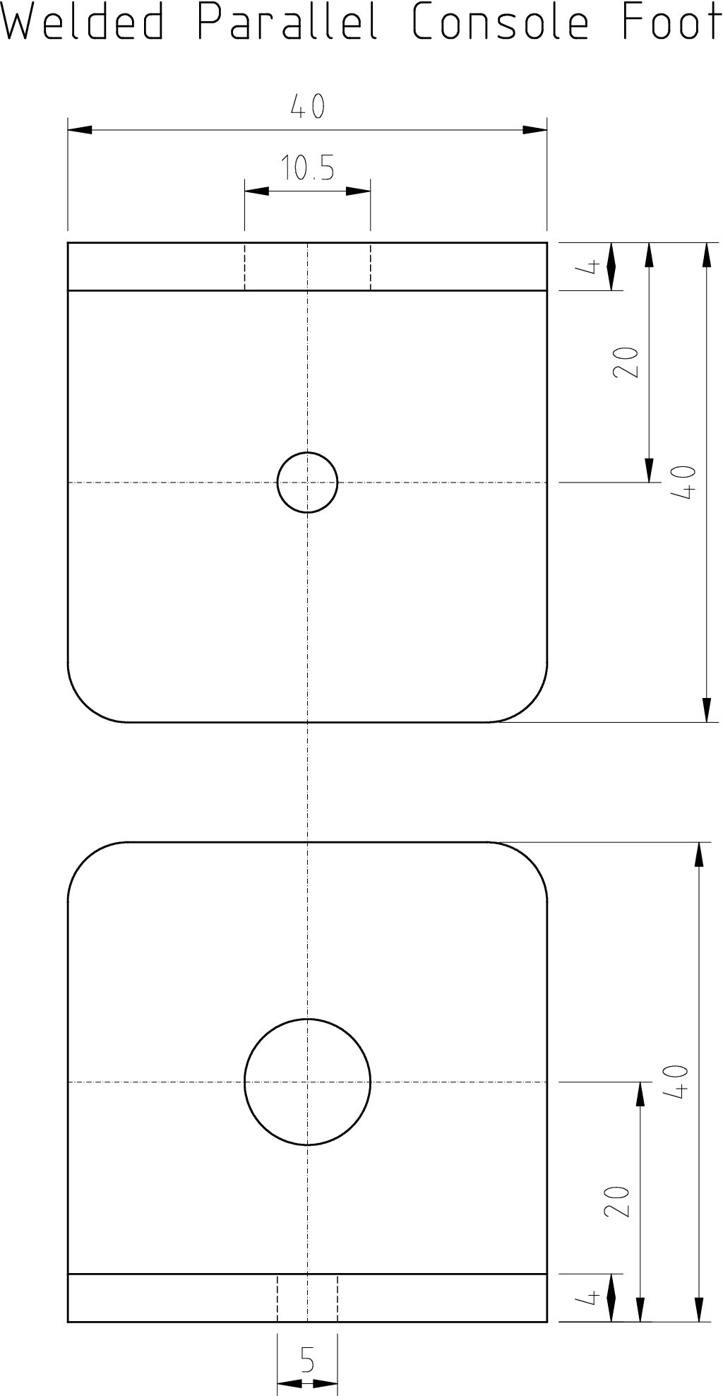
Feet
Manufacture 3 feet according to the drawing from 40x40x4 L steel section,
possibly using previously printed template. Note: the photo
is missing the small hole.
![Gallery[1a4c]](http://images.twibright.com/tns/lvl2/1a4c.jpg) |
|
|
|
|
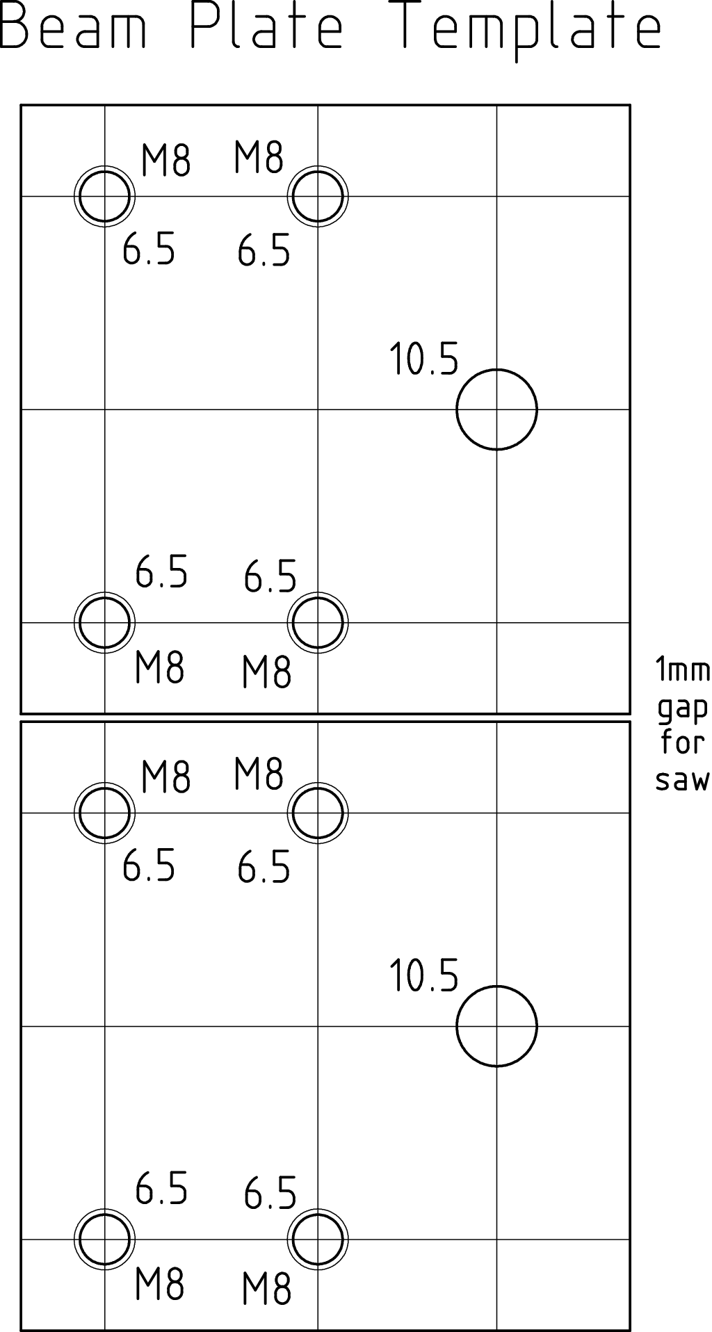
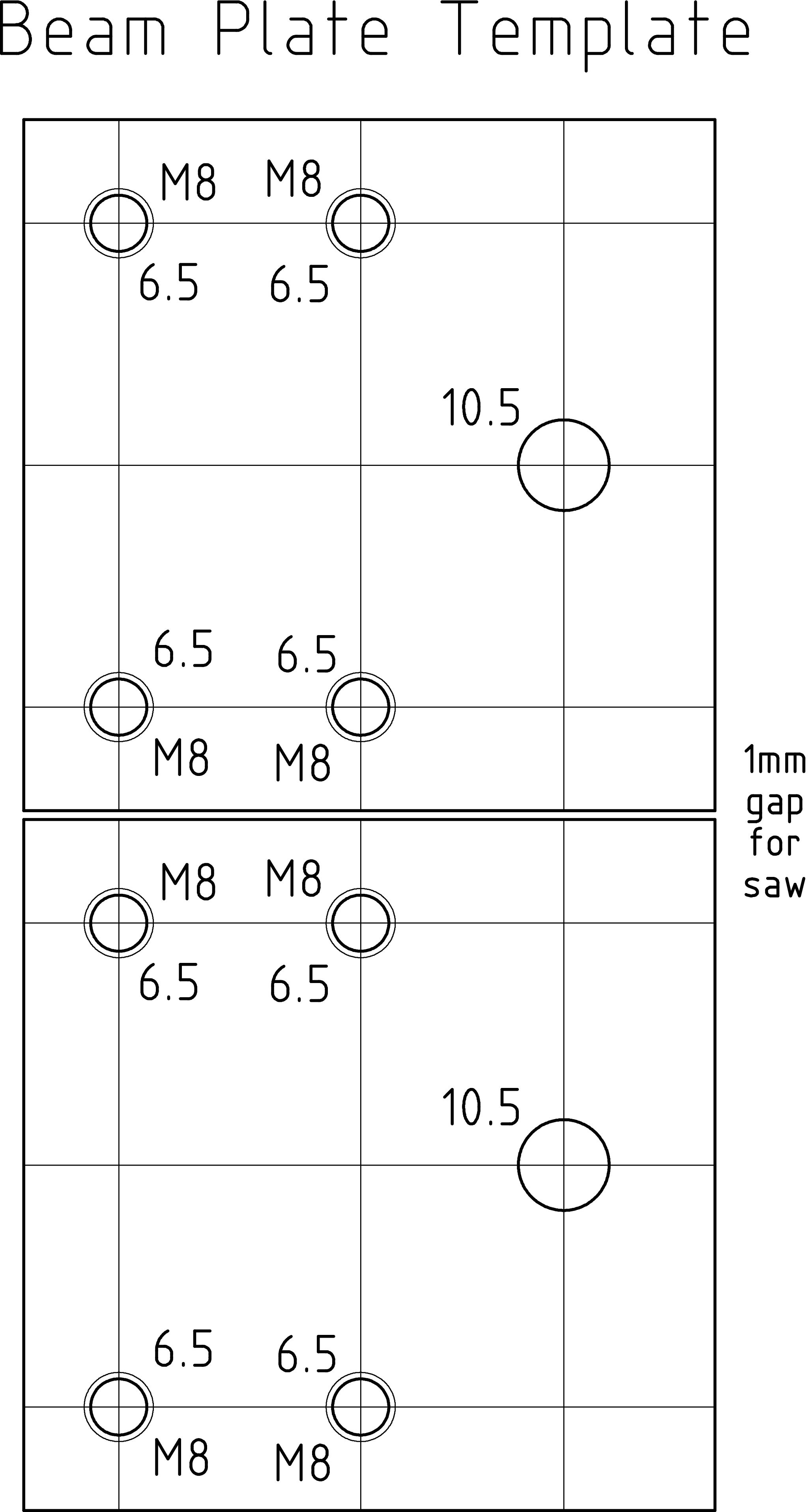
Beam plate template
If you have a precise printer,
print out this template. |
|
|
|
|
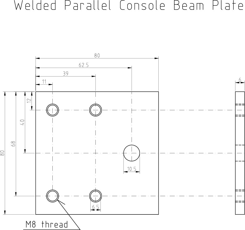
Beam plate
Manufacture 2 beam plates according to the picture, possibly using
previously printed template. |
|
|
|
|
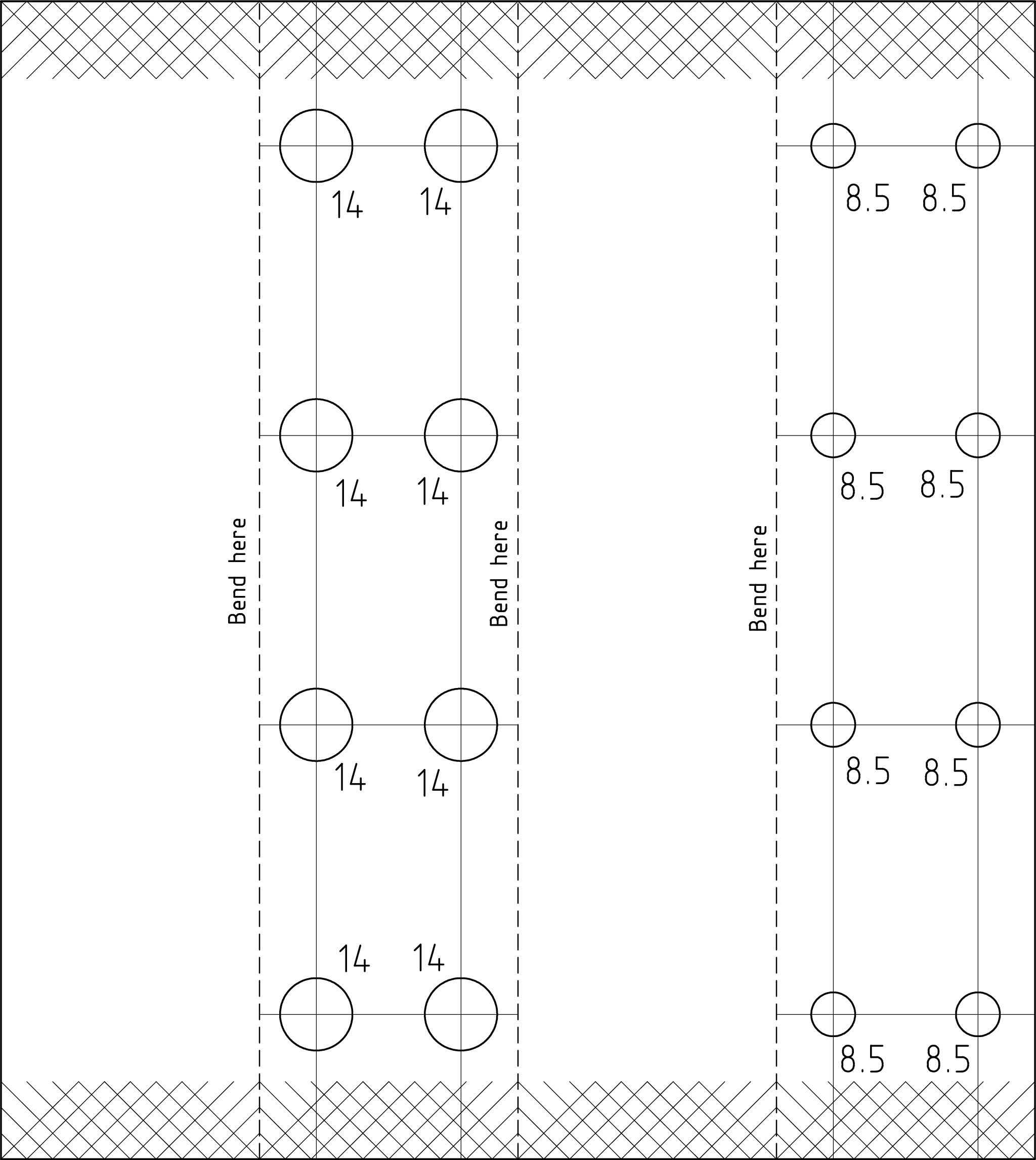
Main beam template
If you have a precise printer,
print out 3 copies of this template. This is for drilling
the holes on the beam. Place the first template from the edge and fit
subsequent templates so the fine lines align smoothly. Note that the templates
provide 12 rows of holes and you are going to drill 11 only. Ignore the
last one. |
|
|
|
|
Main beam
Cut 900mm of 50x50x2 hollow square steel section for the main beam.
Drill out the main beam according to the plan. |
|
|
|
|
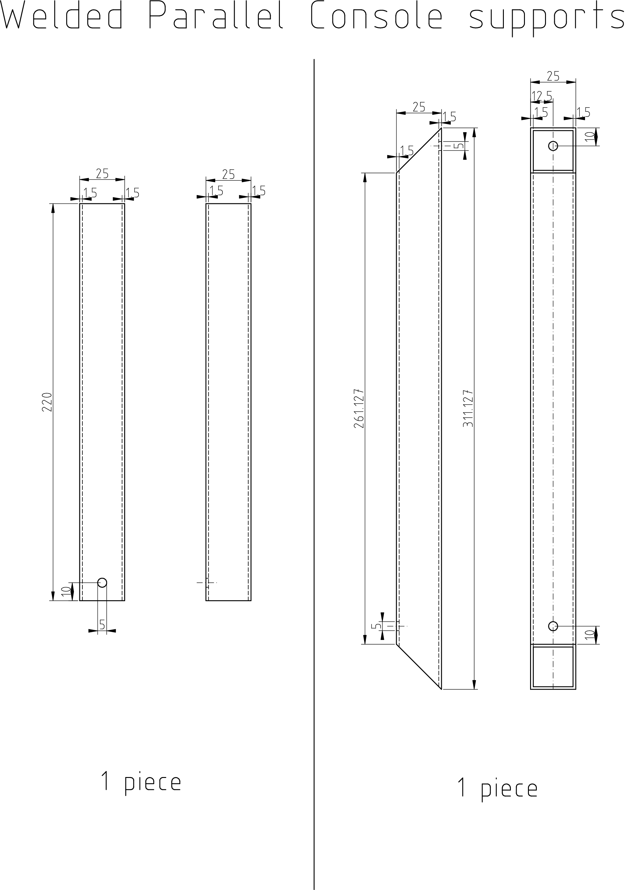
Long Beam supports
Make the pieces indicated from 25x25x2 steel hollow section. You can
place the hole inexactly and use approximate drill diameter. |
|
|
|
|
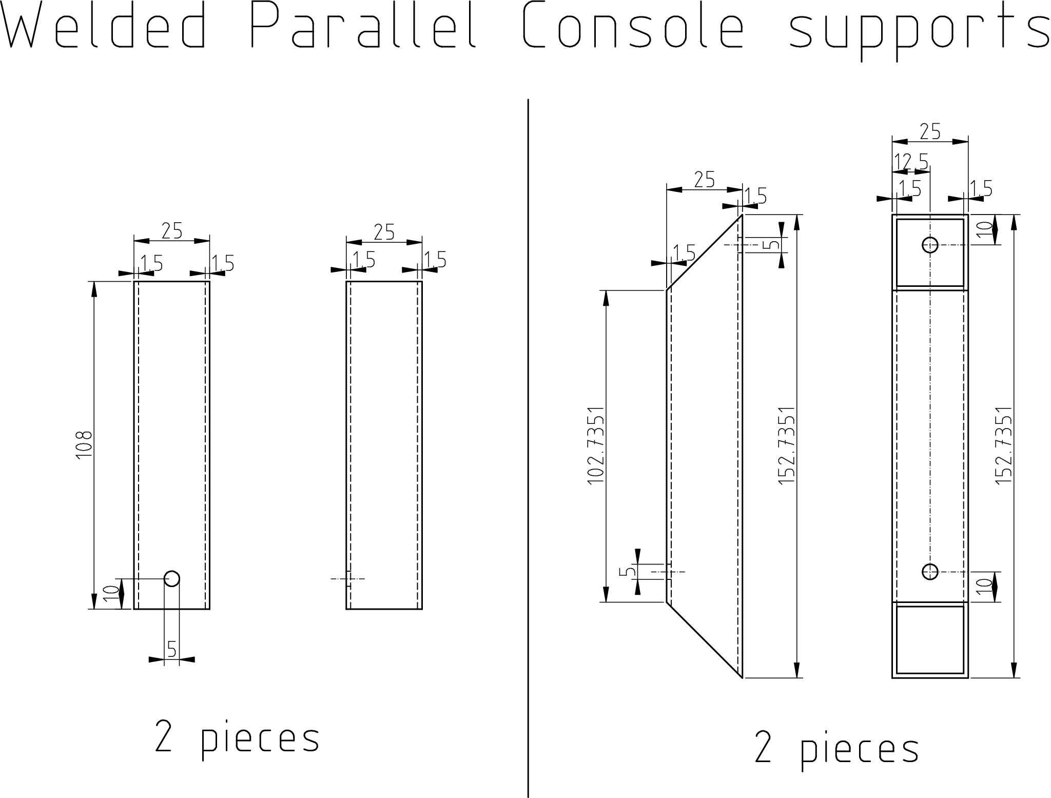
Short Beam supports
Make the pieces indicated from 25x25x2 steel hollow section. You can
place the hole inexactly and use approximate drill diameter. |
|
|
|
| | View | |
|
| | Cutaway View | |
![Gallery[1a54]](http://images.twibright.com/tns/lvl2/1a54.jpg) | | Foot welding detail
Note: on the following picture, the main beam is incorrectly rotated
by 90 degrees.
![Gallery[1a53]](http://images.twibright.com/tns/lvl1/1a53.jpg) | |
|
|
|
Welding
Weld the console according to the 3D model. Make sure the feet are sitting
on a level plane. Make sure zinc drain holes in supports are correctly
positioned. |
|
|
Zinc dip
If you can use zinc dip, have the console zinc dipped.
Clean the threads in beam plates using thread taps number III
(the lowermost one): ![Gallery[13f3]](http://images.twibright.com/tns/lvl0/13f3.jpg) |
|
Powder coating
If you can't use zinc dip but can use powder coating, have the
console powder coated in matte white. After powder coating:
- Clean the threads in beam plates using thread taps number III
(the lowermost one):
- Check for paint burrs and if you find them, grind them flat with
sand paper
|
|
Hand painting
If you cannot neither zinc dip nor powder coat, paint the console by hand
in matte white in water-soluble paint. Use 2 layers of prime paint and 2
layers of top coat. |
|
|
|
Assembly
Assemble the console together according to the cutaway view. |
|
|

 Contact, support: Clock
on the Internet Relay Chat.© 1998-2016 Karel ‘Clock’ Kulhavý et al..
Contact, support: Clock
on the Internet Relay Chat.© 1998-2016 Karel ‘Clock’ Kulhavý et al.. ![Gallery[1a4e]](http://images.twibright.com/tns/lvl1/1a4e.jpg)
![Gallery[1a4d]](http://images.twibright.com/tns/lvl1/1a4d.jpg)
![Gallery[1a4f]](http://images.twibright.com/tns/lvl1/1a4f.jpg)
![Gallery[1a52]](http://images.twibright.com/tns/lvl1/1a52.jpg)
![Gallery[1a4a]](http://images.twibright.com/tns/lvl1/1a4a.jpg)
![Gallery[1a4b]](http://images.twibright.com/tns/lvl1/1a4b.jpg)

![3d/par_welded [0]](/3d/par_welded_0.png)
![3d/par_welded [1]](/3d/par_welded_1.png)
![3d/par_welded [2]](/3d/par_welded_2.png)
![3d/par_welded [3]](/3d/par_welded_3.png)
![3d/par_welded [4]](/3d/par_welded_4.png)

![3d/par_welded_cut [0]](/3d/par_welded_cut_0.png)
![3d/par_welded_cut [1]](/3d/par_welded_cut_1.png)
![3d/par_welded_cut [2]](/3d/par_welded_cut_2.png)
![3d/par_welded_cut [3]](/3d/par_welded_cut_3.png)
![3d/par_welded_cut [4]](/3d/par_welded_cut_4.png)

![Gallery[1a51]](http://images.twibright.com/tns/lvl2/1a51.jpg)
![Gallery[1a50]](http://images.twibright.com/tns/lvl1/1a50.jpg)
![3d/par_welded_we [0]](/3d/par_welded_we_0.png)
![3d/par_welded_we [1]](/3d/par_welded_we_1.png)
![3d/par_welded_we [2]](/3d/par_welded_we_2.png)
![3d/par_welded_we [3]](/3d/par_welded_we_3.png)
![3d/par_welded_we [4]](/3d/par_welded_we_4.png)
