Purpose of the cablesPower exchange cable (W2-PWR) allows both optical heads to share electrical
power. The optical heads take electrical power from shields of the
signal cable(s). Shield of RX signal cable (W1-RX) carries +12V and the shield of the other signal cable (W1-TX) carries
0V (Ground, GND).
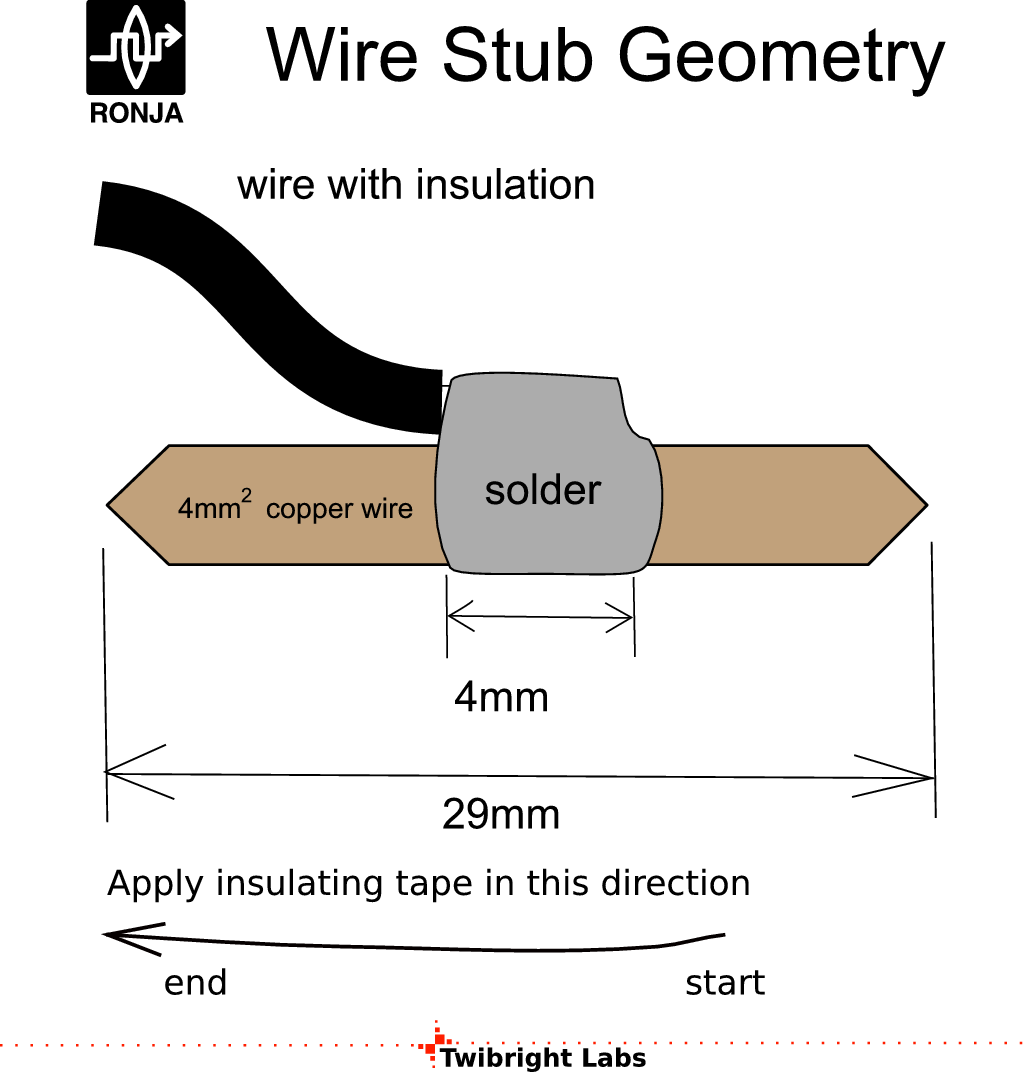
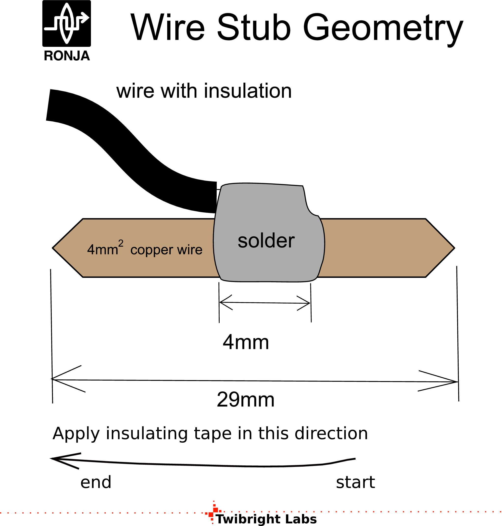
All connectors within Ronja 10M Metropolis system are made of pieces of thick copper
wire (W4). The female is made from electrician's wire nut. The connector is being
secured by tightening a screw. This system ensures reliable contact. This
system also ensures small width of the installed connector male so signal cable
can be pulled through holes when laying in building (through-wall
holes) and installing inside the heads (pulling through holes in the
lids) with connectors (W4) attached. This eliminates
the need to perform soldering on the roof.
A variant to soldered connector would be a crimp-on, but according
to my experience, they
are highly unreliable, especially in outdoor installations. They also
require special (expensive) pliers for mounting.
W3-PROT lightning protection cable protects your home electric installation
from
a fire hazard if lightning strikes directly into the shield of signal
cables (W1) laid on the roof. The undefined contact between the RX and TX shielding
case and the tubular heads' metallic case cannot ensure reliable protection
of in-house electrical installation from absorbing the lightning energy
and setting the house on fire.
| 
 Contact, support: Clock
on the Internet Relay Chat.© 1998-2016 Karel ‘Clock’ Kulhavý et al..
Contact, support: Clock
on the Internet Relay Chat.© 1998-2016 Karel ‘Clock’ Kulhavý et al.. ![Gallery[1176]](http://images.twibright.com/tns/lvl2/1176.jpg)


![Gallery[1172]](http://images.twibright.com/tns/lvl1/1172.jpg)
![Gallery[1c3d]](http://images.twibright.com/tns/lvl1/1c3d.jpg)
![Gallery[1178]](http://images.twibright.com/tns/lvl1/1178.jpg)
![Gallery[1173]](http://images.twibright.com/tns/lvl1/1173.jpg)
![Gallery[115b]](http://images.twibright.com/tns/lvl1/115b.jpg)
![Gallery[117a]](http://images.twibright.com/tns/lvl1/117a.jpg)
![Gallery[13ff]](http://images.twibright.com/tns/lvl1/13ff.jpg)
![Gallery[13b7]](http://images.twibright.com/tns/lvl1/13b7.jpg)
![Gallery[1162]](http://images.twibright.com/tns/lvl1/1162.jpg)
![Gallery[1400]](http://images.twibright.com/tns/lvl1/1400.jpg)
![Gallery[13b8]](http://images.twibright.com/tns/lvl1/13b8.jpg)
![Gallery[1c3e]](http://images.twibright.com/tns/lvl1/1c3e.jpg)
![Gallery[117b]](http://images.twibright.com/tns/lvl1/117b.jpg)
![Gallery[1176]](http://images.twibright.com/tns/lvl1/1176.jpg)